
Unboxing, and build of new HD-Plex H5 Silent PC
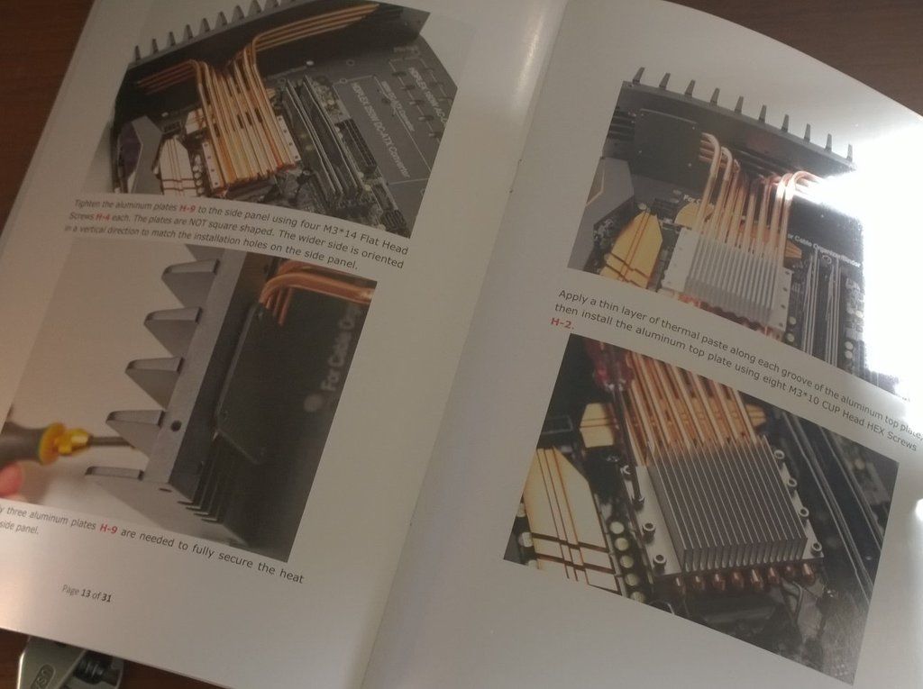
Overall the build is very straightforward if you follow the instructions in the Guide.
Everything lined up perfectly and nothing needed to be bashed or fettled to get it to fit.
Machining quality is really superb.
All parts were present and correct in neat little bags and trays for easy identification.
I of course had to modify the design slightly so I made myself some extra work, but I got an even better unit for my needs/wants.
Final Parts List
HD-Plex H5 Gen2 Silent PC Case (Direct)
ASRock Z97 Extreme6/3.1 (Amazon)
Intel i5 5675c Broadwell (Overclockers UK)
HD-PLex AC-DC 160W + DC-ATX 250W Power Supply (Direct)
Corsair Vengence Pro 16GB 1866 (SCAN)
Samsung 950 Pro SSD 500GB (OC UK)
KingWin 2.5 + 3.5 + USB3.0 Drive Bay (5.25) (Amazon USA)
LG GS40N DVD (Ultra Slim Slot Loading Writer) (Kikatek)
Windows 8.1 Pro (eBay from Latvia)
Additions to Standard Kit
10x M3x10mm Cup head screw
4x slim M3 nut
2x Aluminium plate 16 Guage 170mm x 80mm
Background . . .
I have been looking to build a silent PC for quite a while and kept looking at Streacom passive cases but last time I searched for ideas I came across the HD-Plex site and found that these cases were much better and about the same price. More options for internals with a passive GPU option up to say Nvidea 950, a TDP of 95W for both CPU and GPU plus amazing design and build quality.
I was initially going to build around an i5 6600K Skylake but then MS decided to stop support for Skylake going forward with Win 8.1, so I went back to the drawing board and discovered that the i5 5675C was the same power consumption with better onboard graphics. I was starting with no GPU as I probably don't need one at the moment.
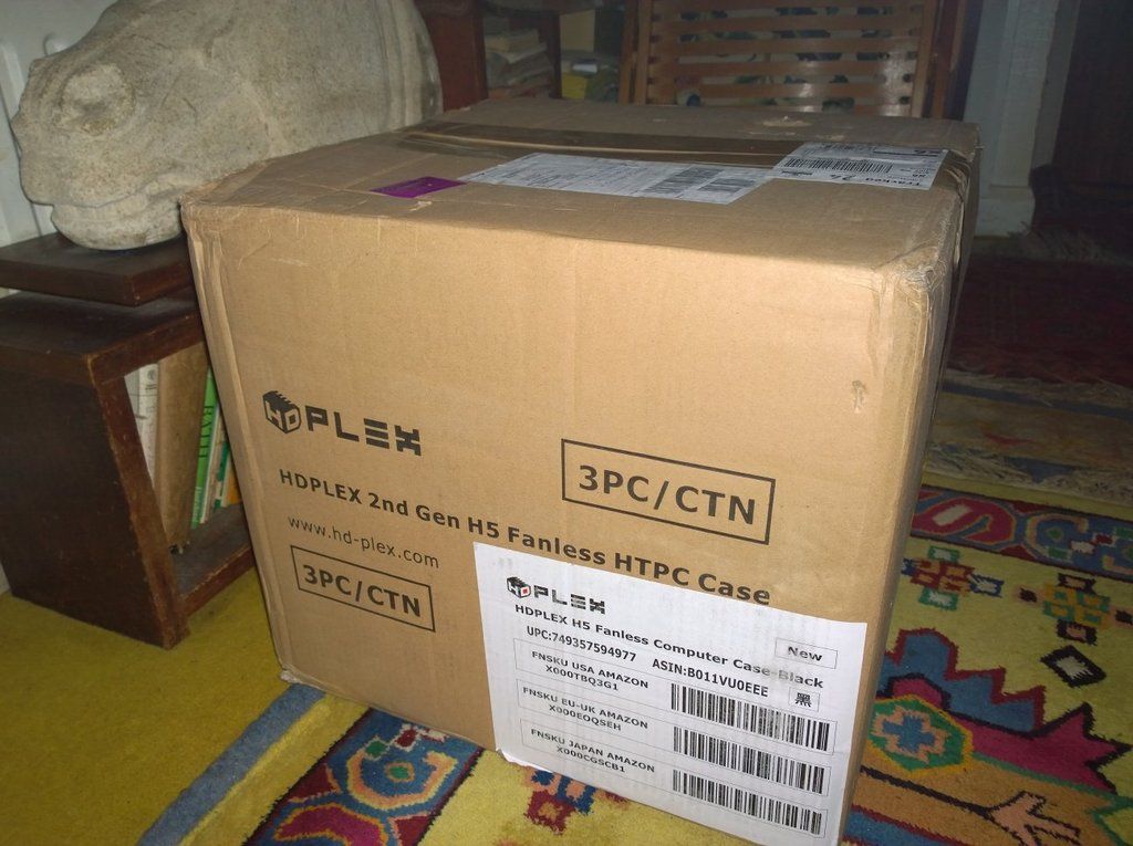
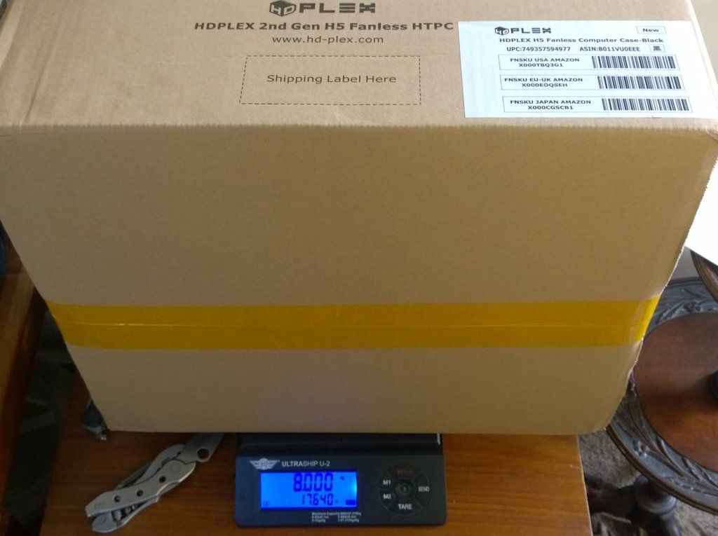
Part One - Unboxing.
Case arrives from German distribution hub.
Contents (without packing foam sheets)
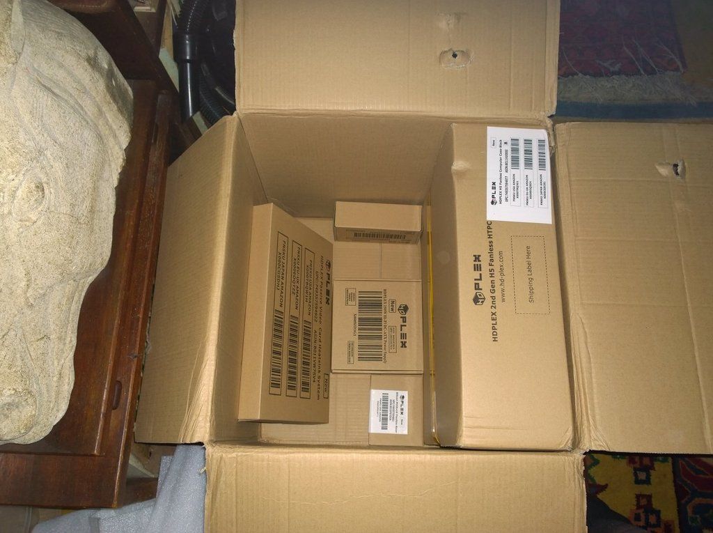
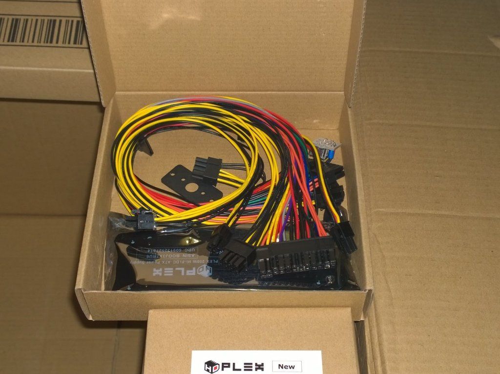
DC-ATX 250W PSU Box
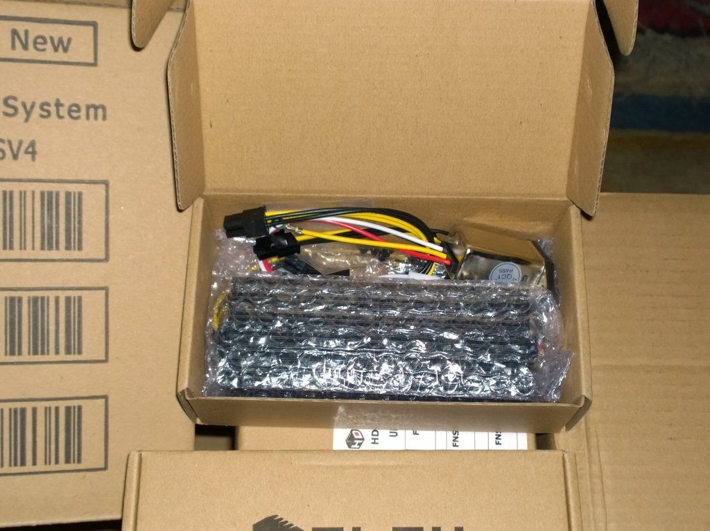
AC-DC 160W PSU Box
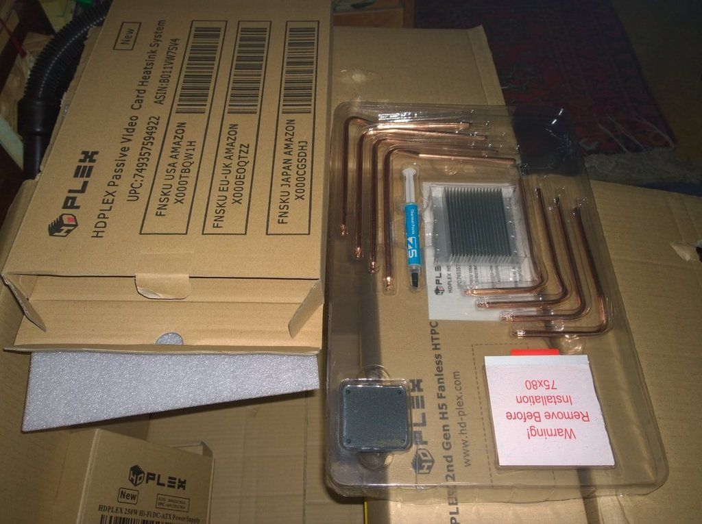
GPU Passive Cooler Box (Future Option)
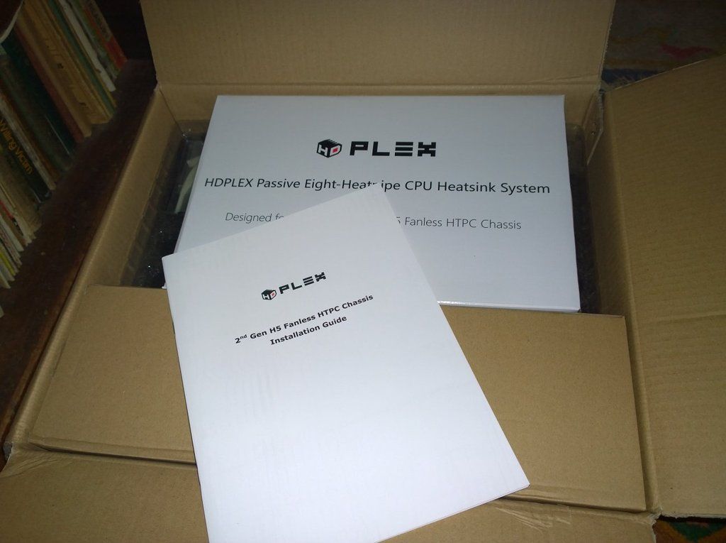
Main Case Box : Printed Manual - Front Panel - Parts Tray - Case Parts
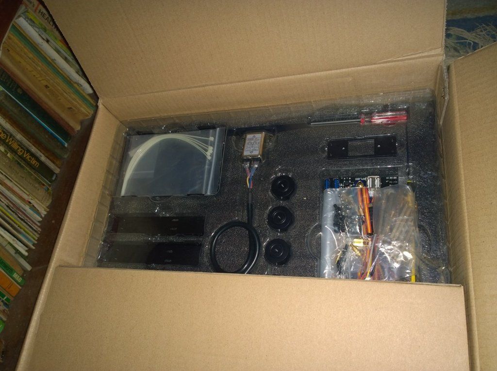
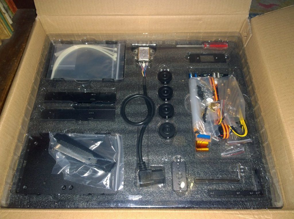
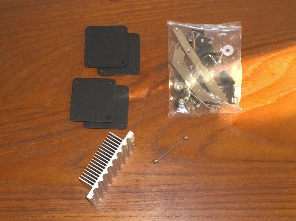
Main Parts Tray
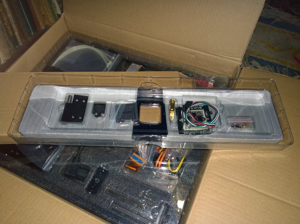
Front Panel Parts Tray
Closer look - Main Parts Tray
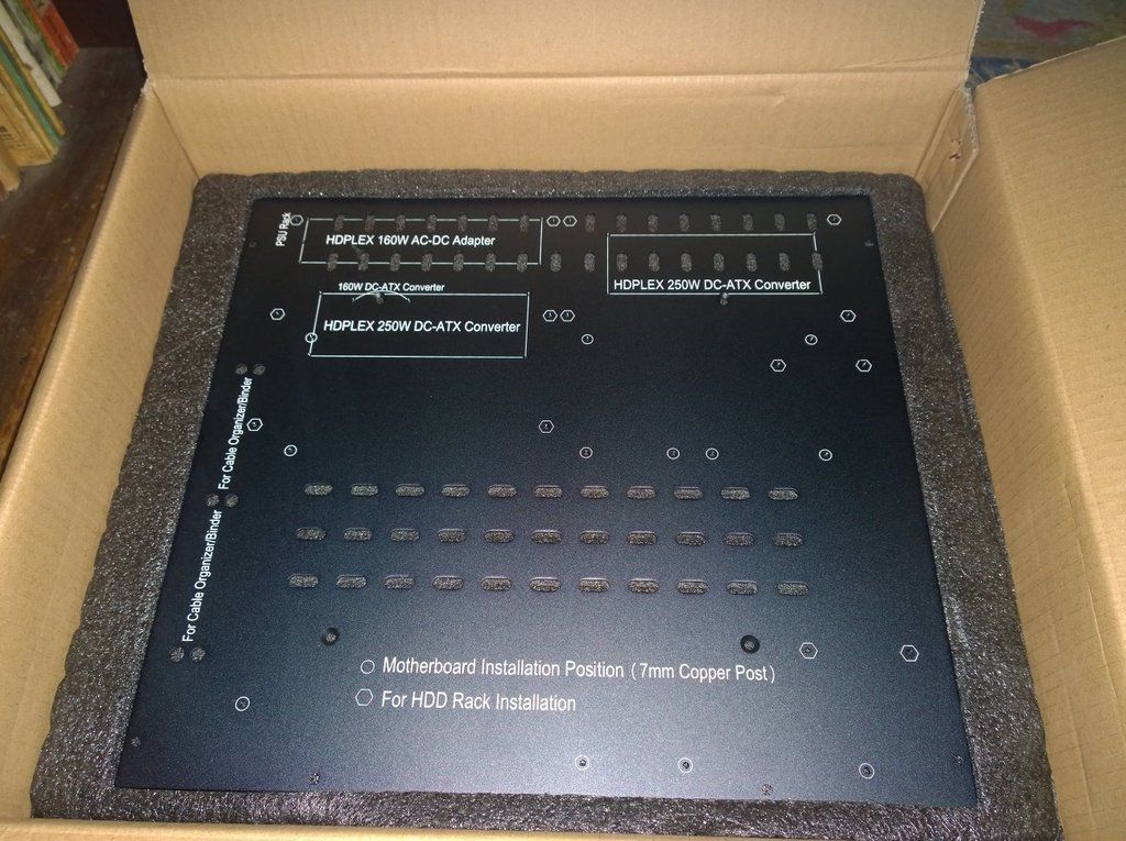
Case Bottom Panel - Inner side
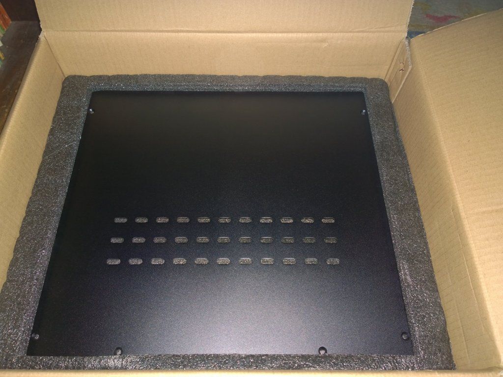
Top Panel
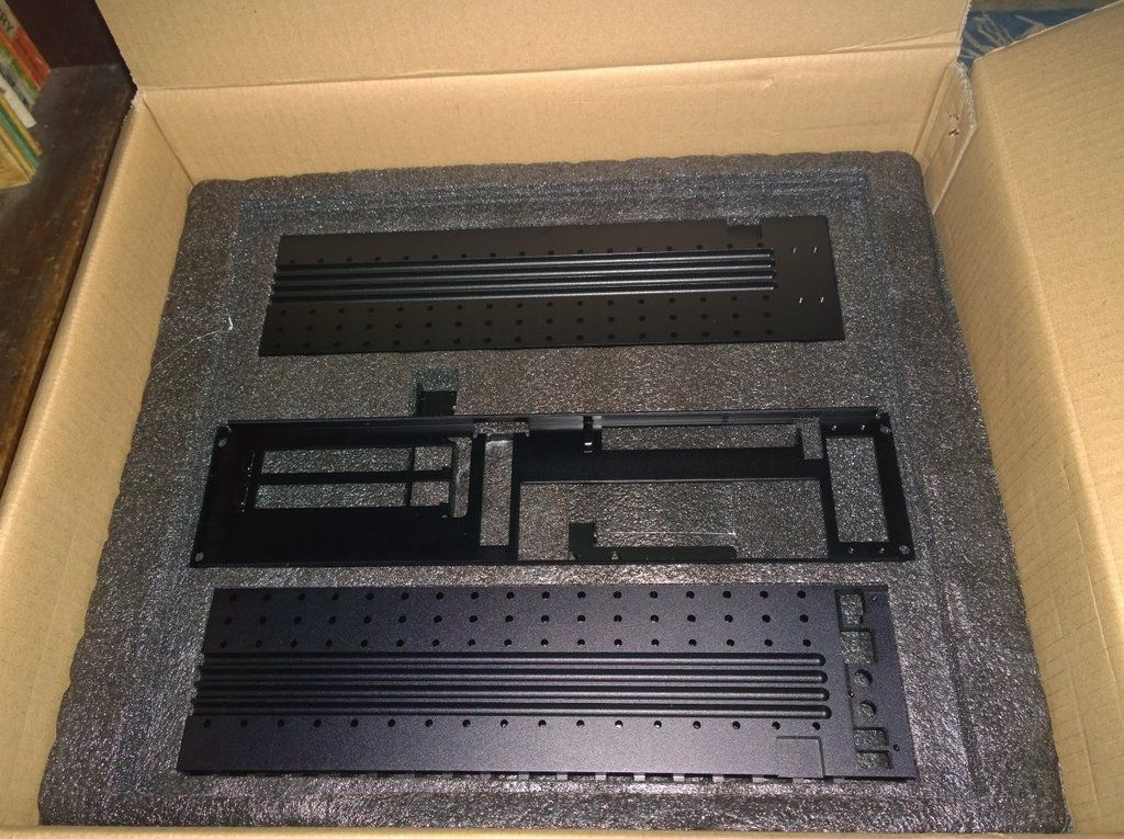
Sides and Rear Panel
Case Boxed weighs 8Kg
Glossy Instructions
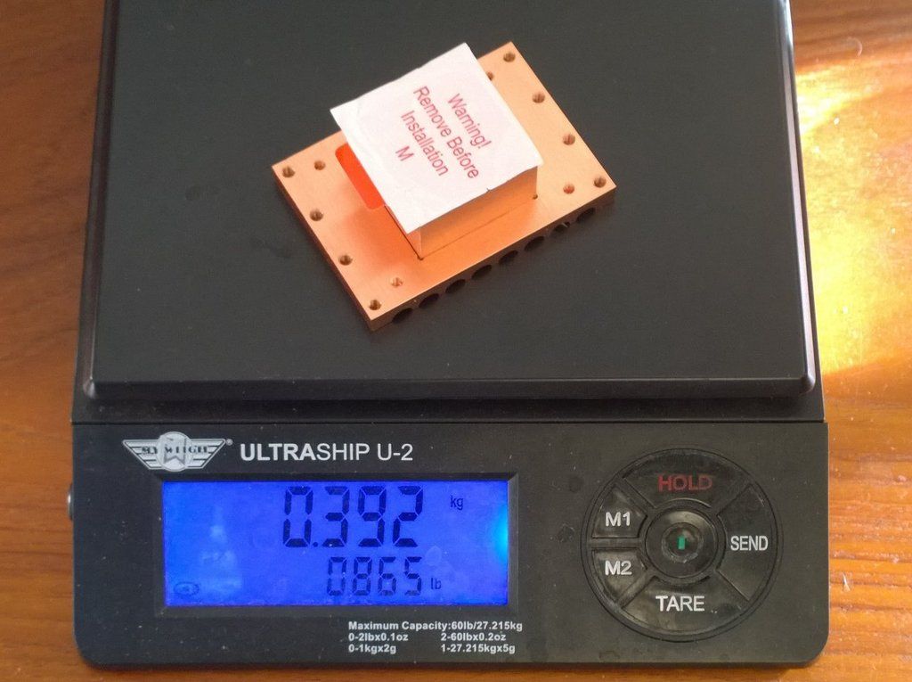
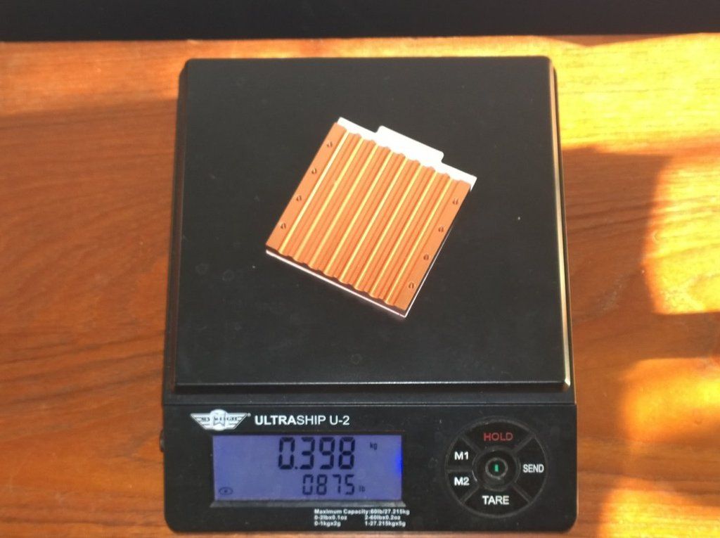
Solid Copper CPU Heatsink
Heatpipes
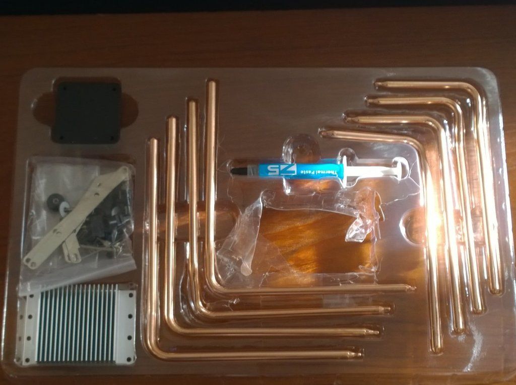
CPU Cooler Plate and side panel heat-pipe plates
GPU Cooler
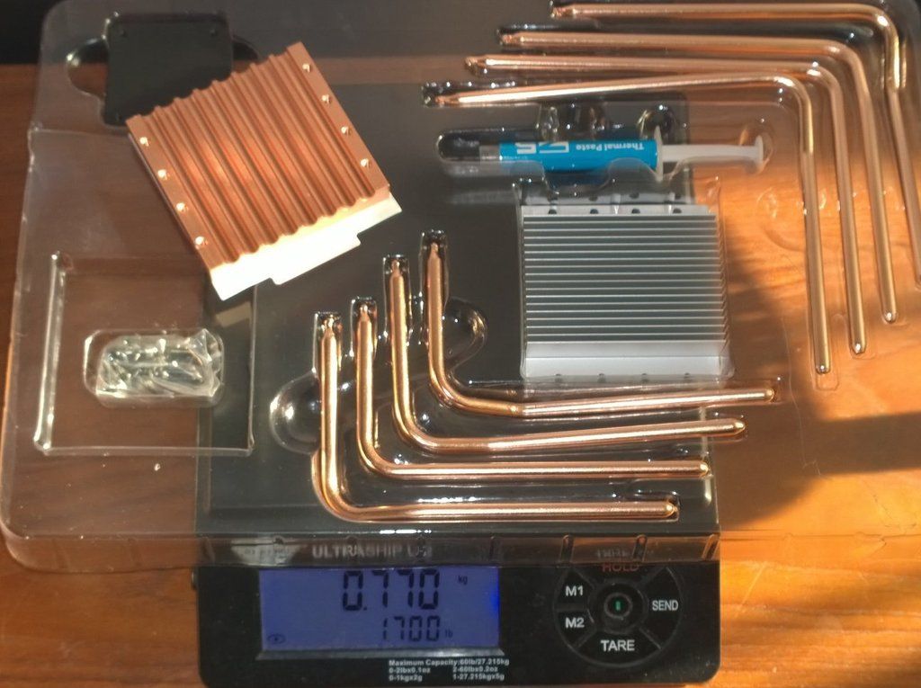
Solid Copper
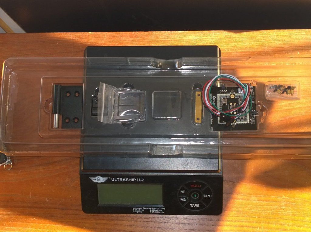
Front Panel Illuminated Touch Switch parts tray
Next - The Build . . .
: )


