Antec Phantom Disassembled

PSUs: The source of DC power for all components in the PC & often a big noise source.

Moderators: NeilBlanchard, Ralf Hutter, sthayashi, Lawrence Lee, Devonavar

Post Reply
blackworx
*Lifetime Patron*
Posts: 601
Joined: Sat Dec 01, 2007 2:04 am
Location: UK

Antec Phantom Disassembled

Post by blackworx » Fri Apr 04, 2008 7:49 am

Hi folks,

My name's Bruce, I've been into PC silencing and reading SPCR for a few years, but only recently joined the forums. I'm still somewhat of a noob, as this is the first forum I've ever posted (and wanted to post) to with any regularity. I'm a programmer from Edinburgh and I like puppies and long walks in the park on autumn days, ooh and open fires and and and... Yeah you get the idea. Anyway, hi! :D

On to the reason for the post... I bought a Phantom 500W back in December and it turned out to be faulty. Because of the weight and cost for shipping it back to Antec in the Netherlands (about a quarter of the price I paid for it in the first place, which I wasn't willing to pay) they instructed me to cut the cable loom, send them a photo, then dispose of the PSU.

The thing is, there's nothing wrong with the supply - apart from a VERY loud ringing or buzzer noise which starts anywhere from 5 minutes to 2 hours after power-on. It hasn't failed or faltered at any point and doesn't apparently overheat - at least the external shell never reaches anything like a dangerous temperature.

I detest waste and really couldn't bring myself to throw an essentially-functional piece of equipment in the bin, plus I know at least one other person has had the exact same issue, so I decided to open it up and take a look. If I could find the malfunction then so much the better but, from a brief Google, there aren't yet any disassemblies online so I figured I could satisfy other folks' curiosity as well...

Opening it up wasn't too difficult. Once the fan assembly and external socket plate are removed, logic dictates that the top plate (which is keyed to the sides) should slide off, but that isn't the case. It's held in place longitudinally with a couple of inaccessible pins, so you have to lift the lid off vertically. It's a tight interference fit, but comes away with a bit of steady leverage.

The lid has several thick pieces of white thermal transfer material, all of which were obviously in good contact with their respective components and heatsinks (no photo, sorry). The only concern I would have is with the thickness of the material itself (~1mm) but then I'm no expert and I'm sure it does its job just fine. Also I guess it would be very hard to engineer the component and heatsink placement to a much higher tolerance anyway.

(Most photos click for full size)

Image

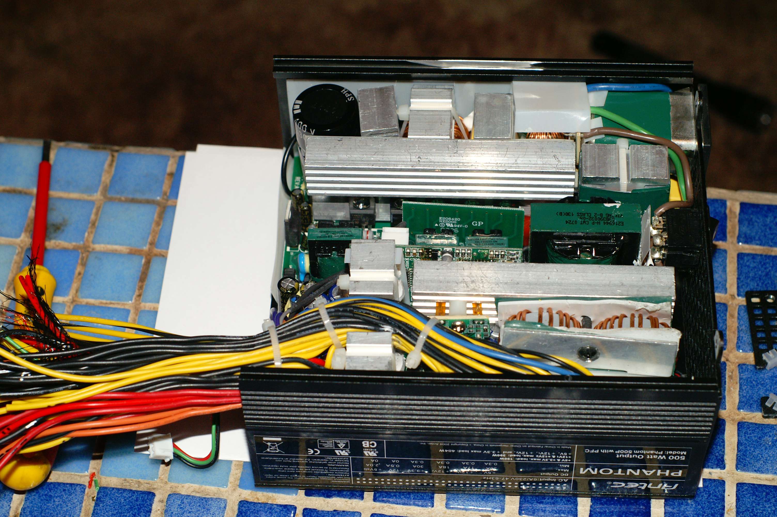
The box is truly jammed with components. There are numerous daughter boards and ICs - something I can't recall ever seeing many of in other supplies. Not visible in the photo is a thermistor which I believe is for the fan controller. It is fastened to the base of the large heatsink in the top half of the picture.

The next step was to start the supply, leave it for a couple of hours and hope the fault would manifest itself. Unfortunately it didn't, despite the internal heatsinks getting quite seriously hot. So it would appear the fault only happens under load.

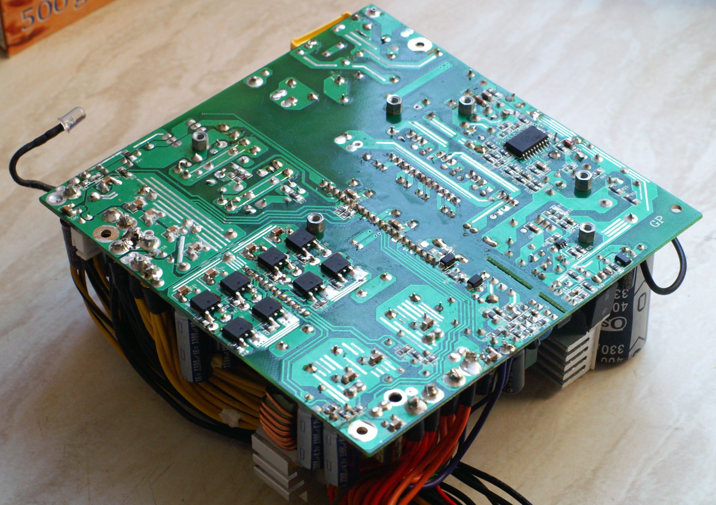
Before going on to test the unit under load, we decided to remove the board to get a look in the sides and underneath. This is where the surprise lay.

Image

It's not immediately obvious from this picture but the board is, frankly, a mess. There are about 50% dry joints, lots of waste flux, and some very messy work indeed. Also, if you look closer...

Image

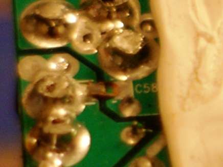
Was the capacitor destroyed before final assembly, or has it blown clean off because of a fault? The remains of it are definitely still there on the board, but there was no debris in the case or scorch marks etc. to suggest the magic smoke got out at any point.

Also not visible in that photo, but nearby, one of the PCB tracks at the edge is sheared almost clean off the board.

Any experts out there who know anything about surface mount capacitors and their behaviour under stress? Anybody know what might have caused this, other than it being snapped off after the board was assembled? If so please let me know, because I don't have a clue.

Image

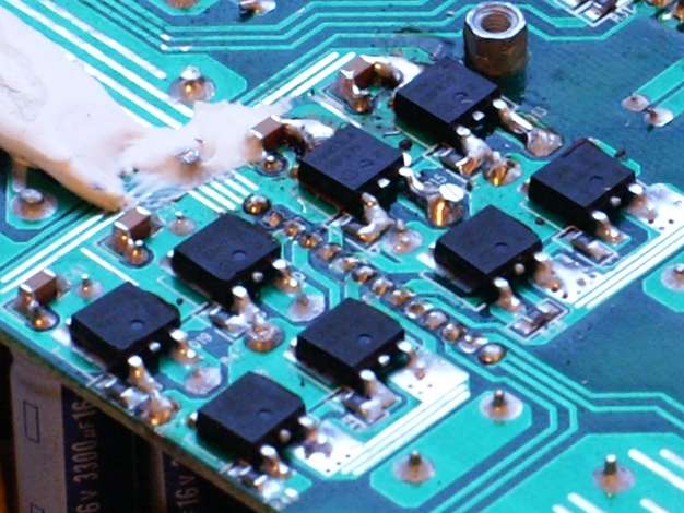
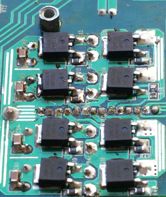
These huge gobs of solder on the mosfets are also a mystery. Some of them were much bigger but have been chopped off. Anyone know of a legitimate reason why it should be like that?

Image

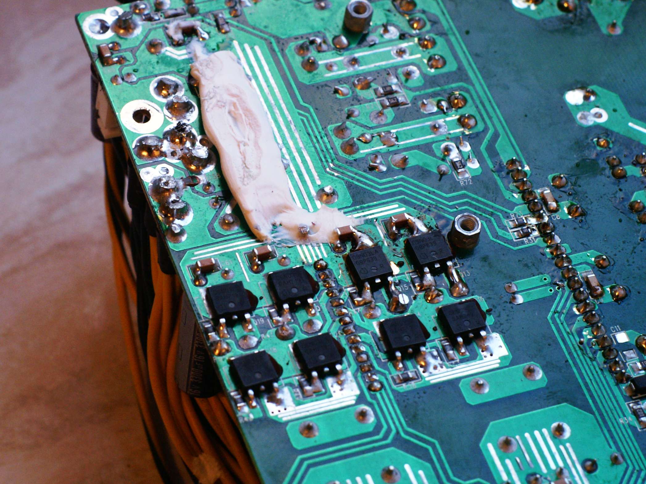
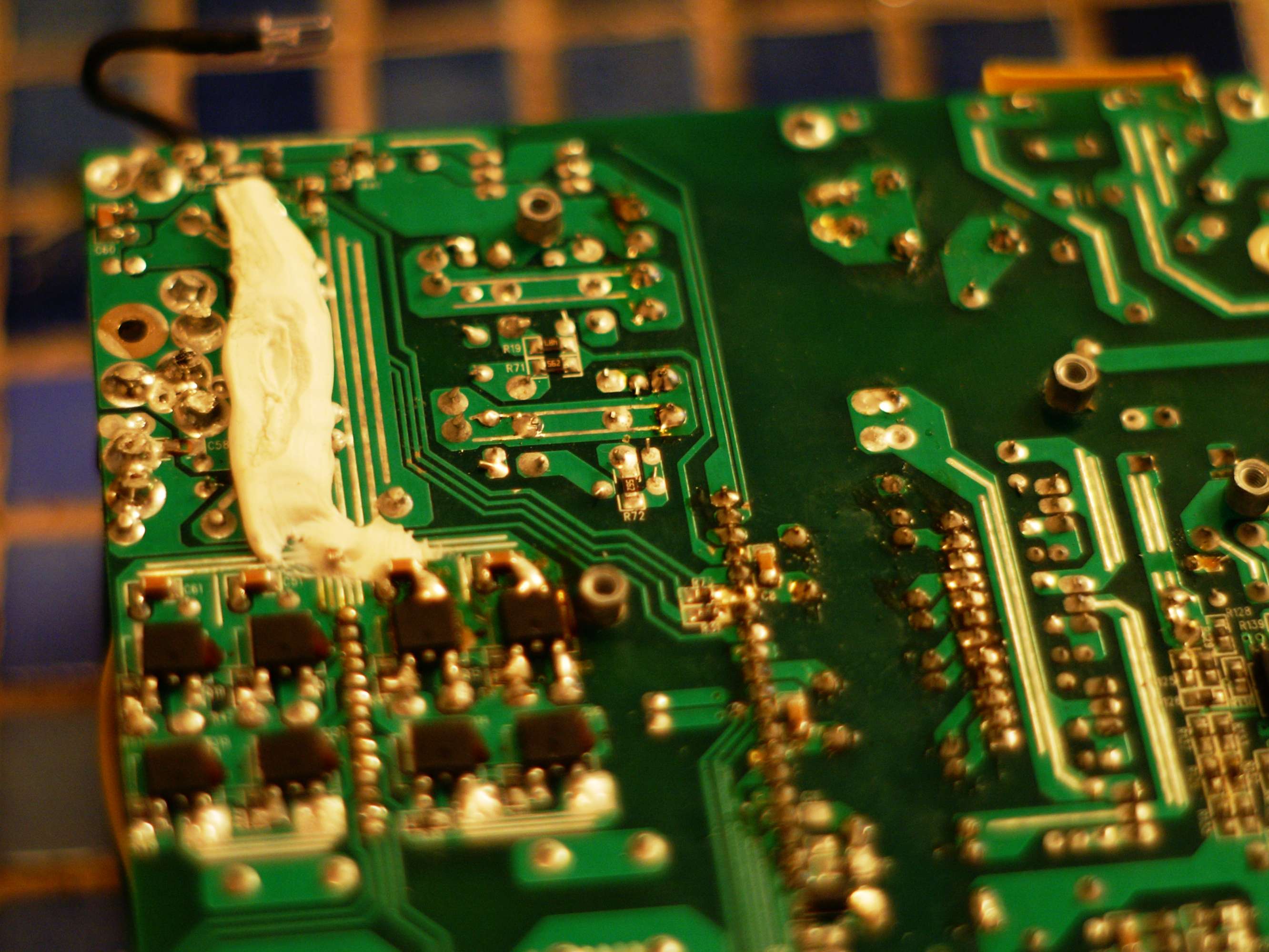
The above photo, taken in better light than the first one, shows the general mess slightly better. The big gob of silicone is directly beneath the wire loom area and two big coils which are both shrouded with smaller heatsinks (see top photo). I'm guessing it's there to fill the gap on the underside in order to stop the wires from pushing the heatsinks out of contact with the lid. I can think of more elegant solutions.

All in all I'm very surprised with the low standard of workmanship in this supply and I wonder whether it was remanufactured (badly) from a warranty return. If all Phantom 500's are this badly built, it would seem to bear out the higher-than-average failure rate suggested by MikeC's poll. Or am I making a big fuss out of nothing? Anyone from Antec care to comment? (PS: Antec - sorry I didn't throw out the supply as agreed - I couldn't resist having a look!)

Next step is to clean up the PCB and resolder as many of the joints as possible, but I don't know what to do about the busted capacitor. Any PSU gurus out there care to comment, or even offer some guidance?

Finally, props to my housemate Paul for helping with this (it's his pet project)!

antifro
Posts: 39
Joined: Tue Jun 14, 2005 10:52 pm
Location: NYC

Post by antifro » Fri Apr 04, 2008 8:20 am

As a Phatom 500 owner of almost 3 years, I vote for a sticky! I'm curious of what will happen. Thanks and welcome!

tehcrazybob
Friend of SPCR
Posts: 356
Joined: Wed Jan 16, 2008 8:56 pm
Location: Council Bluffs, Iowa
Contact:

Post by tehcrazybob » Fri Apr 04, 2008 8:52 am

Does the solder in my red circles bridge anything that doesn't look like it ought to be bridged?

Image[/img]

blackworx
*Lifetime Patron*
Posts: 601
Joined: Sat Dec 01, 2007 2:04 am
Location: UK

Tidied up a bit

Post by blackworx » Sat Apr 05, 2008 1:18 am

antifro wrote:As a Phatom 500 owner of almost 3 years, I vote for a sticky! I'm curious of what will happen. Thanks and welcome!
Cheers!
tehcrazybob wrote:Does the solder in my red circles bridge anything that doesn't look like it ought to be bridged?
Nope - they were all clear.

My housemate spent all afternoon while I was at work yesterday tidying up the PCB and a couple of the daughter boards where he could. This is the end result (click for bigger):

Image

Image

The only dry joints he couldn't redo were the external wiring anchors - too big for my iron to melt. If I get time today I will reassemble the supply and test it under load.

Oh, and here is another detail shot of the inside, showing the thermistor mentioned in my first post. I think this one is actually for the thermal overload circuit, as what look more like the fan control thermistors are higher up and half-embedded in the fins of the same heatsink:

Image

Still not sure what to do about the missing capacitor - anyone in the know care to advise me what effect its absence will be having?

charlaph
Patron of SPCR
Posts: 32
Joined: Mon Jan 31, 2005 1:20 pm
Location: Dundee, Scotland

Post by charlaph » Tue Apr 15, 2008 7:18 am

Very interesting Bruce. Looking forward to you retesting it to see if it cures the random noise issue. I'm also pretty astonished at the condition of the circuit board - do you reckon it's a recon?

vick1000
Posts: 81
Joined: Sat Dec 24, 2005 11:52 pm
Location: Jax FL

Post by vick1000 » Sat Apr 19, 2008 4:24 am

Good God!!!! That is one shoddy built unit.

The noise is probably coming from those uninsulated torroid coils. You can coat them in liquid electrical tape if you can get to them. The missing cap looks like it might be bridging the 12v leads, which might give tham a little more noise/ ripple at load (it looks like there was never anything there, just fluxed). You didn't find the missing cap somewhere?

yukon
Posts: 61
Joined: Tue Jul 26, 2005 12:25 pm
Location: Canada

Post by yukon » Sat Apr 19, 2008 12:10 pm

Awful. I solder better than that, and I never learned how properly. I vote for the sticky as well, and suggest that this kind of quality control should be looked at in SCPR reviews if it is not already (it probably is). That PCB looks like someone poured melted solder on to save time.

Under the red circles, it doesn't look like that should be bridged, since that could have been done in the PCB design. If it is supposed to be bridged, then poor design instead of just poor manufacturing.

blackworx
*Lifetime Patron*
Posts: 601
Joined: Sat Dec 01, 2007 2:04 am
Location: UK

Post by blackworx » Tue Apr 22, 2008 5:37 am

vick1000 wrote:The noise is probably coming from those uninsulated torroid coils. You can coat them in liquid electrical tape if you can get to them.
Agreed.
And if, as seems apparent, this supply has been pulled to bits and "repaired" on more than one occasion, then I suppose it should come as no surprise that some coil windings are now loose.
You didn't find the missing cap somewhere?
Nope - not even a grain of dust! One thing I have noticed in my photos that I didn't see before is that the HS mounting bolts look like they have been attacked with a monkey wrench :shock: ... Yet again I'm amazed this thing ever worked at all.

Apologies for the delay folks. I hope to get this reassembled and, with a little luck, operational soon. Currently mucking around with my new build which is getting in the way of everything else.

Avalanche
Posts: 137
Joined: Mon May 29, 2006 6:29 am
Location: IN, USA
Contact:

Post by Avalanche » Tue Apr 22, 2008 9:39 am

blackworx wrote:I hope to get this reassembled and, with a little luck, operational soon.
Well, best of luck, but I wouldn't bet money on it. :wink:

EdT
Posts: 88
Joined: Sun Dec 19, 2004 10:11 pm
Location: Montreal, Canada

Post by EdT » Sun Jul 27, 2008 8:00 pm

That is some sloppy workmanship standards, it does even look like Class 1 IPC-A-610 standards since computer equipment is suppose to be Class 2 !

I would also resolder all the joints that were sheared off since fractures and cracks can result from it.

IPC-A-610 states for Class 2 all sheared off joints must be invidually inspected with a 10x loop for fractures or touched up ! I doubt any of those joint were inspected at all.

"Antec after seeing this, your Phantom line of power supplies does not justify the high cost !"

I expect at least IPC-A-610 Class 2 standards for this level of equipment !

It is no wonder with bad workmanship standards and poor choice of component selection that the Phantom line of power supply have such a high defect rate leading the demise of this product and the confidence of fellow enthuaists who shell out the big bucks for something that is of much lessor quality !

blackworx
*Lifetime Patron*
Posts: 601
Joined: Sat Dec 01, 2007 2:04 am
Location: UK

Post by blackworx » Mon Jul 28, 2008 4:36 am

EdT wrote:I would also resolder all the joints that were sheared off since fractures and cracks can result from it.
We tried to, but unfortunately they are too big for my little 25W iron :( ... Some of those sheared joints are bone dry, so I may use it as an excuse finally to invest in a proper iron.
It is no wonder with bad workmanship standards and poor choice of component selection that the Phantom line of power supply have such a high defect rate leading the demise of this product and the confidence of fellow enthuaists who shell out the big bucks for something that is of much lessor quality !
Well said. My guess is that this particular Phantom has been back to the factory on multiple occasions and has been butchered - presumably by p*ssed off service/recon guys who hated working with it and knew the product was a lost cause.

This project's on the back burner for now, but I do still intend to pot the coils and reassemble it at some point. It certainly won't be put to use with any new kit though. At most it'll be used to power an HTPC built from ancient/reclaimed parts.

EdT
Posts: 88
Joined: Sun Dec 19, 2004 10:11 pm
Location: Montreal, Canada

Post by EdT » Mon Jul 28, 2008 8:13 am

blackworx wrote:
EdT wrote:I would also resolder all the joints that were sheared off since fractures and cracks can result from it.
We tried to, but unfortunately they are too big for my little 25W iron :( ... Some of those sheared joints are bone dry, so I may use it as an excuse finally to invest in a proper iron.
It is no wonder with bad workmanship standards and poor choice of component selection that the Phantom line of power supply have such a high defect rate leading the demise of this product and the confidence of fellow enthuaists who shell out the big bucks for something that is of much lessor quality !
Well said. My guess is that this particular Phantom has been back to the factory on multiple occasions and has been butchered - presumably by p*ssed off service/recon guys who hated working with it and knew the product was a lost cause.

This project's on the back burner for now, but I do still intend to pot the coils and reassemble it at some point. It certainly won't be put to use with any new kit though. At most it'll be used to power an HTPC built from ancient/reclaimed parts.
Try to find a Hakko 936 or Hakko clone soldering station, one of the best low cost units around in the industry.

blackworx
*Lifetime Patron*
Posts: 601
Joined: Sat Dec 01, 2007 2:04 am
Location: UK

Post by blackworx » Mon Jul 28, 2008 8:53 am

Cheers EdT - will do :)

Post Reply