My circuit for using 3 pin fans on 4 pin PWM mobo headers
Posted: Sat May 10, 2008 7:19 am
Been an age since I last posted here.
Apologies if I am teaching my Granny to suck eggs here, but I searched not just here but all over and couldn't find a circuit published anywhere that does this. The only similar circuit I could find anywhere was just blatantly wrong.
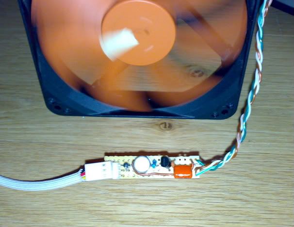
Its a simple circuit that seems to work very well.
I checked out the standards for 4 pin mobo connections. The important things to note are.
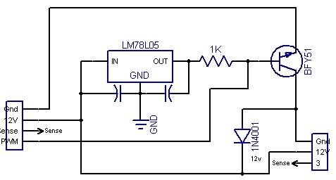
The mobo header works in open drain on pin 4 to provide the PWM signal to the fan. The mobo's are capable of draining 5mv of current minimum.. That is why I used a 1k pullup resistor. I reckon i could have used higher no probs.
The fan itself requires a 3-5v pullup, ie the mobo pwm controller does not supply voltages. Hence the reason for the LM78L05 voltage regulator.
The circuit above uses a BFY51 medium power transistor. The 12v fan I have tried it on is rated at 0.3A. With an Hfe of 120 on my multimeter, and 5 mv of current at the base, this circuit should be good for supplying two fans at a push. I have several BFY51's that have higher HFe and so could comfortably supply two 120mm fans.
Why that particular transistor? Well its NPN. Can handle 800mv of current no problem, and most importantly I had some in my parts bin that I had no other use for.
The rest of the circuit is easy. As a motor (fan) is an inductive load, it does not require a current limiting resistor. The only other part of importance is the 4n4001 diode between the +/- pins of the 3 pin fan. The motor is an inductive load, so when swithing off produces voltage spikes. The diode is there to protect against them.
I made up this circuit this afternoon and it works as intended. Comparing it to the standard 3 pin PWM function on my Mobo there are some advantages to using this circuit.
The PWM from the 4 pin header seems smoother and quieter.
The 4 pin PWM does allow the fan to be controlled down to a much slower speed. On speedfan I managed to get the 120mm thermaltake fan I had (Origionally supplied with a Typhoon heatsink) controlled to 5% in free air and running fairly reliably. This was giving around 60rpm (the fan cannot report to the computer its rpm at these speeds. 6% was totally reliable and still a lot slower than the mobo's 3 pin header could control.
Disadvantages...
Speedfan cannot measure the RPM through the sense wire of the fan very well at all with this circuit. Spurious readings occur frequently when PWM is applied.
Its obviously not as easy as just plugging in to a 3 pin header. Though parts wise the costs are minimal.
I have to admit that if I had realised in the first place that speedfan would control my 3 pin header I probably would not have bothered designing this... But hey it is a bit of a novelty seing a 120mm fan spin so slowly you can count the rpm.
***Schematic edited due to carelessness of the author***
JB
Apologies if I am teaching my Granny to suck eggs here, but I searched not just here but all over and couldn't find a circuit published anywhere that does this. The only similar circuit I could find anywhere was just blatantly wrong.
Its a simple circuit that seems to work very well.
I checked out the standards for 4 pin mobo connections. The important things to note are.
The mobo header works in open drain on pin 4 to provide the PWM signal to the fan. The mobo's are capable of draining 5mv of current minimum.. That is why I used a 1k pullup resistor. I reckon i could have used higher no probs.
The fan itself requires a 3-5v pullup, ie the mobo pwm controller does not supply voltages. Hence the reason for the LM78L05 voltage regulator.
The circuit above uses a BFY51 medium power transistor. The 12v fan I have tried it on is rated at 0.3A. With an Hfe of 120 on my multimeter, and 5 mv of current at the base, this circuit should be good for supplying two fans at a push. I have several BFY51's that have higher HFe and so could comfortably supply two 120mm fans.
Why that particular transistor? Well its NPN. Can handle 800mv of current no problem, and most importantly I had some in my parts bin that I had no other use for.
The rest of the circuit is easy. As a motor (fan) is an inductive load, it does not require a current limiting resistor. The only other part of importance is the 4n4001 diode between the +/- pins of the 3 pin fan. The motor is an inductive load, so when swithing off produces voltage spikes. The diode is there to protect against them.
I made up this circuit this afternoon and it works as intended. Comparing it to the standard 3 pin PWM function on my Mobo there are some advantages to using this circuit.
The PWM from the 4 pin header seems smoother and quieter.
The 4 pin PWM does allow the fan to be controlled down to a much slower speed. On speedfan I managed to get the 120mm thermaltake fan I had (Origionally supplied with a Typhoon heatsink) controlled to 5% in free air and running fairly reliably. This was giving around 60rpm (the fan cannot report to the computer its rpm at these speeds. 6% was totally reliable and still a lot slower than the mobo's 3 pin header could control.
Disadvantages...
Speedfan cannot measure the RPM through the sense wire of the fan very well at all with this circuit. Spurious readings occur frequently when PWM is applied.
Its obviously not as easy as just plugging in to a 3 pin header. Though parts wise the costs are minimal.
I have to admit that if I had realised in the first place that speedfan would control my 3 pin header I probably would not have bothered designing this... But hey it is a bit of a novelty seing a 120mm fan spin so slowly you can count the rpm.
***Schematic edited due to carelessness of the author***
JB