
Thanks Leila, glad you're enjoying the read! Yeah, a lot of time spent on this project. Will try and get more updates up soon.leila wrote:
Wow, I just can imagine the amount of time you took to build the radiator. It looks so laborious. Thumbs up to you man and I hope you could continue on with the work and post the finished product so I could admire it more
Project: Hush!
Moderators: NeilBlanchard, Ralf Hutter, sthayashi, Lawrence Lee
-
Monkey Puzzle
- Posts: 37
- Joined: Tue Apr 13, 2010 5:14 am
- Location: UK
Last edited by Monkey Puzzle on Mon Oct 11, 2010 2:33 pm, edited 1 time in total.
-
Monkey Puzzle
- Posts: 37
- Joined: Tue Apr 13, 2010 5:14 am
- Location: UK
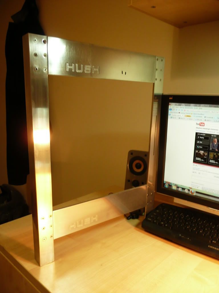
Thanks Xobim. I'm going to do a bit more countersinking in a week to get them all flush with the aluminium frame.Xobim wrote:That is some brilliant aluminium work, even though the screws aren't exactly flush with the surface. Do post some pictures with the front on the case.
By the way, are you going to polish the copper fins aswell? They got pretty ugly when you heated up the solder slinkies with the torch.
Regarding the the copper fins, I know what you mean - they were so pretty before the heat and crappy flux. The copper was a lot pinker after the bead-blasting, though now they're all a bit oxidised. I think I'm going to have them all black by dipping them in Liver of Sulphur solution. Should make them radiate a LOT more heat and be such a thin patina that conductive heat transfer isn't lessened too much. Going to anodise the aluminium black or a dqark carbon/gunmetal grey. Should hopefully look pretty slick.
-
Monkey Puzzle
- Posts: 37
- Joined: Tue Apr 13, 2010 5:14 am
- Location: UK
Re: Project: Hush!
Time for an update. 
I decided to replace the backpanel I'd used from another case that has the fan hole. It's a bit dusty.
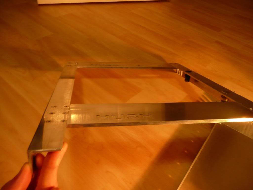
I wanted to have a simple aluminium back panel.
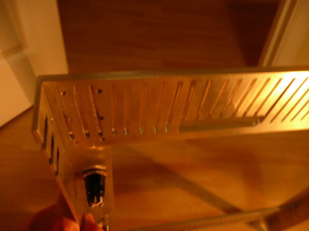
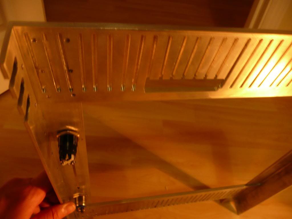
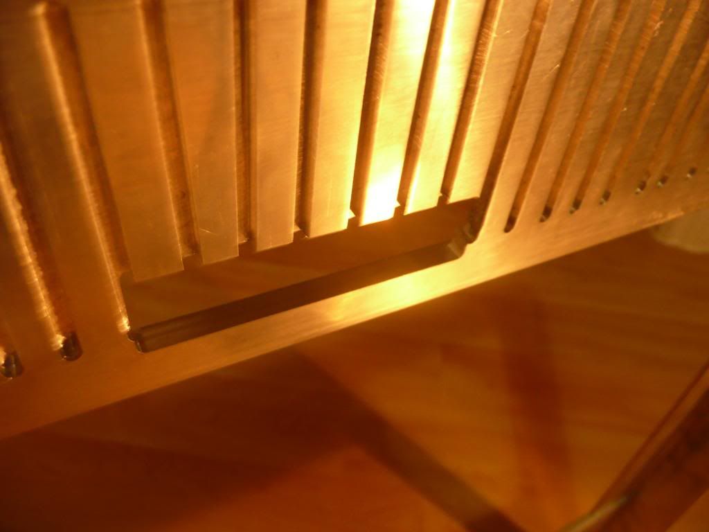
To have it sit flush with the aluminium frame a 10mm x 1.5mm step was milled from the inside side of the aluminium top and bottom frame and a 1.5mm sheet of aluminium cut and filed to leave the 1.5mm back panel sitting flush with the frame on the inside:
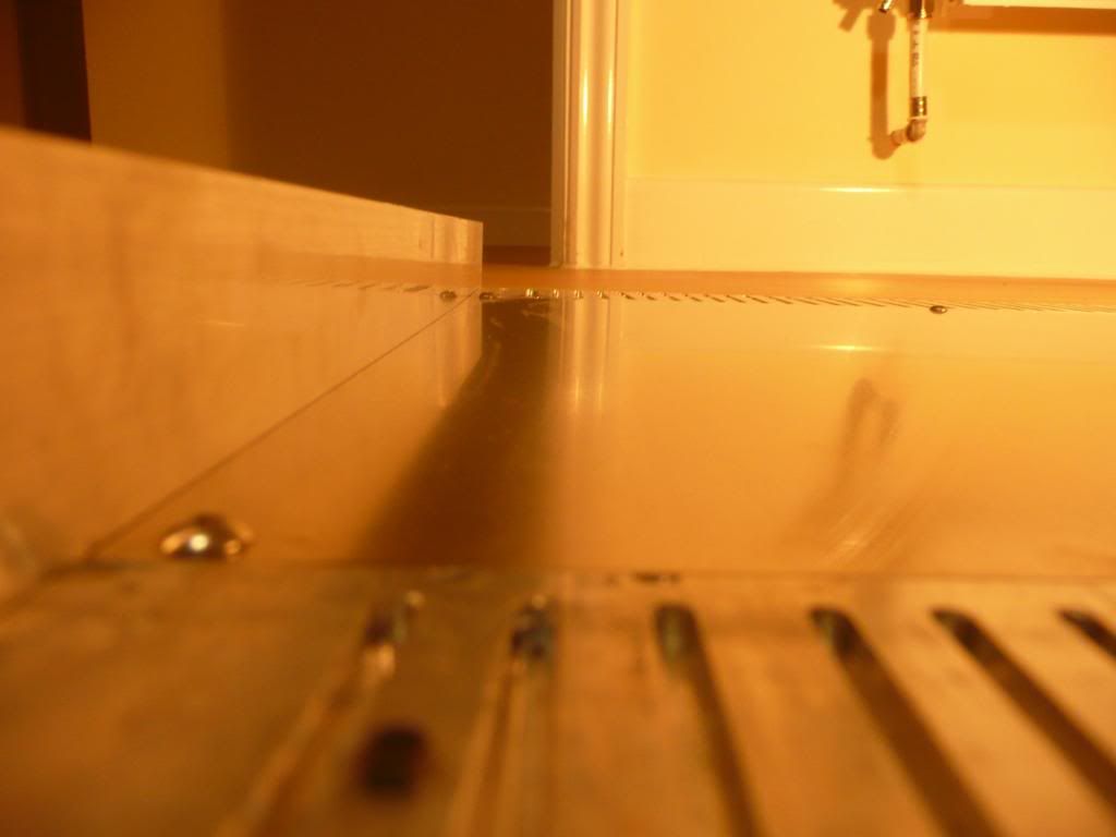
Next thing will be to cut out the hole for the I/O and PCI bracket to sit it in. This is going to be inserted from the back so you can't see the folded aluminium of the motherboard tray where it attaches to give a cleaner look when viewing from the inside of the case.
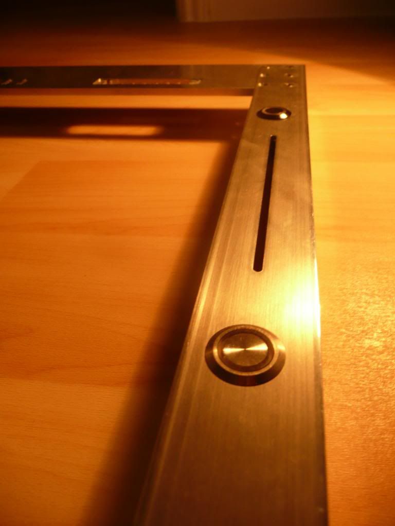
I used a stepped drill to make the 2 19mm holes for the antivandal switches; one for power, and one will be wired up to replace for the button of the slot-loading slimline dvd drive.
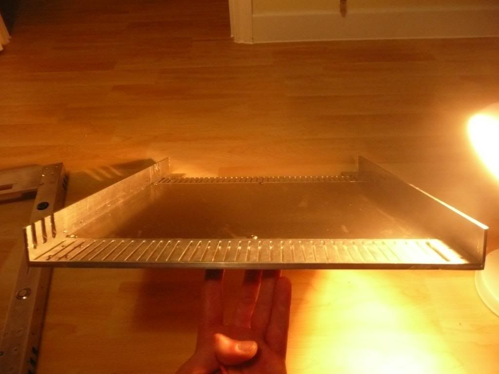
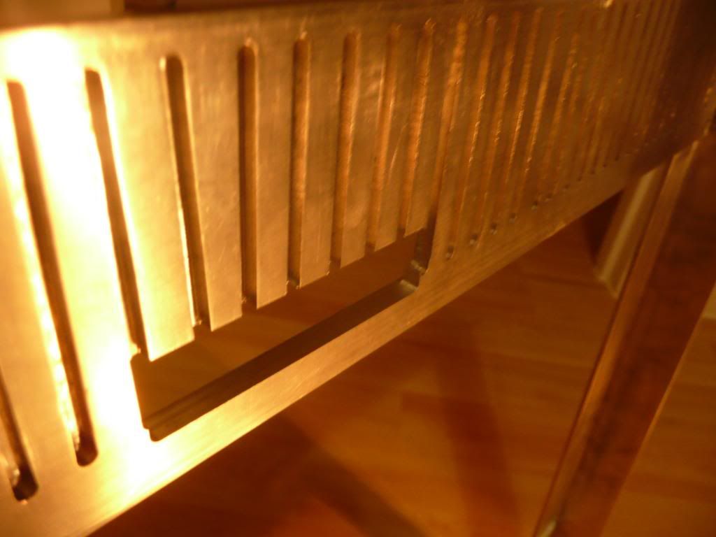
There had previously been holes in the 1/4 aluminium frame that were made from machining bits breaking when milling the slots the copper fins sit in as so:
To hide these I had a 1.5mm deep stepped section cut out for an aluminium cover plate to sit in. This will have front panel ports; USB (USB 3 if I can find some), audio, eSATA and firewire ports, and will allow me to make a new cover panel for different ports etc in future whilst securing the aluminium panel to the copper fins with resin.
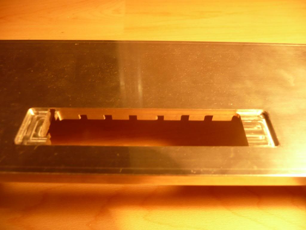
I also did a little more countersinking to make the screwheads sit nice and flush.
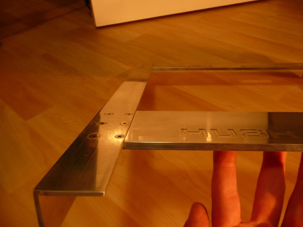
Still a bit more to do on some of them though.
I decided to replace the backpanel I'd used from another case that has the fan hole. It's a bit dusty.
I wanted to have a simple aluminium back panel.
To have it sit flush with the aluminium frame a 10mm x 1.5mm step was milled from the inside side of the aluminium top and bottom frame and a 1.5mm sheet of aluminium cut and filed to leave the 1.5mm back panel sitting flush with the frame on the inside:
Next thing will be to cut out the hole for the I/O and PCI bracket to sit it in. This is going to be inserted from the back so you can't see the folded aluminium of the motherboard tray where it attaches to give a cleaner look when viewing from the inside of the case.
I used a stepped drill to make the 2 19mm holes for the antivandal switches; one for power, and one will be wired up to replace for the button of the slot-loading slimline dvd drive.
There had previously been holes in the 1/4 aluminium frame that were made from machining bits breaking when milling the slots the copper fins sit in as so:
To hide these I had a 1.5mm deep stepped section cut out for an aluminium cover plate to sit in. This will have front panel ports; USB (USB 3 if I can find some), audio, eSATA and firewire ports, and will allow me to make a new cover panel for different ports etc in future whilst securing the aluminium panel to the copper fins with resin.
I also did a little more countersinking to make the screwheads sit nice and flush.
Still a bit more to do on some of them though.
-
grimreeper
- Posts: 15
- Joined: Sat Apr 12, 2008 2:28 am
- Location: Australia
Re: Project: Hush!
This is epic! 
I worry when a cpu cooler puts the strength of my motherboards socket to the test but this, this would probably snap my desk. When I was reading the start I thought you were going to put this giant cooler on your cpu for the lol's .
.
I worry when a cpu cooler puts the strength of my motherboards socket to the test but this, this would probably snap my desk. When I was reading the start I thought you were going to put this giant cooler on your cpu for the lol's
-
Monkey Puzzle
- Posts: 37
- Joined: Tue Apr 13, 2010 5:14 am
- Location: UK
Re: Project: Hush!
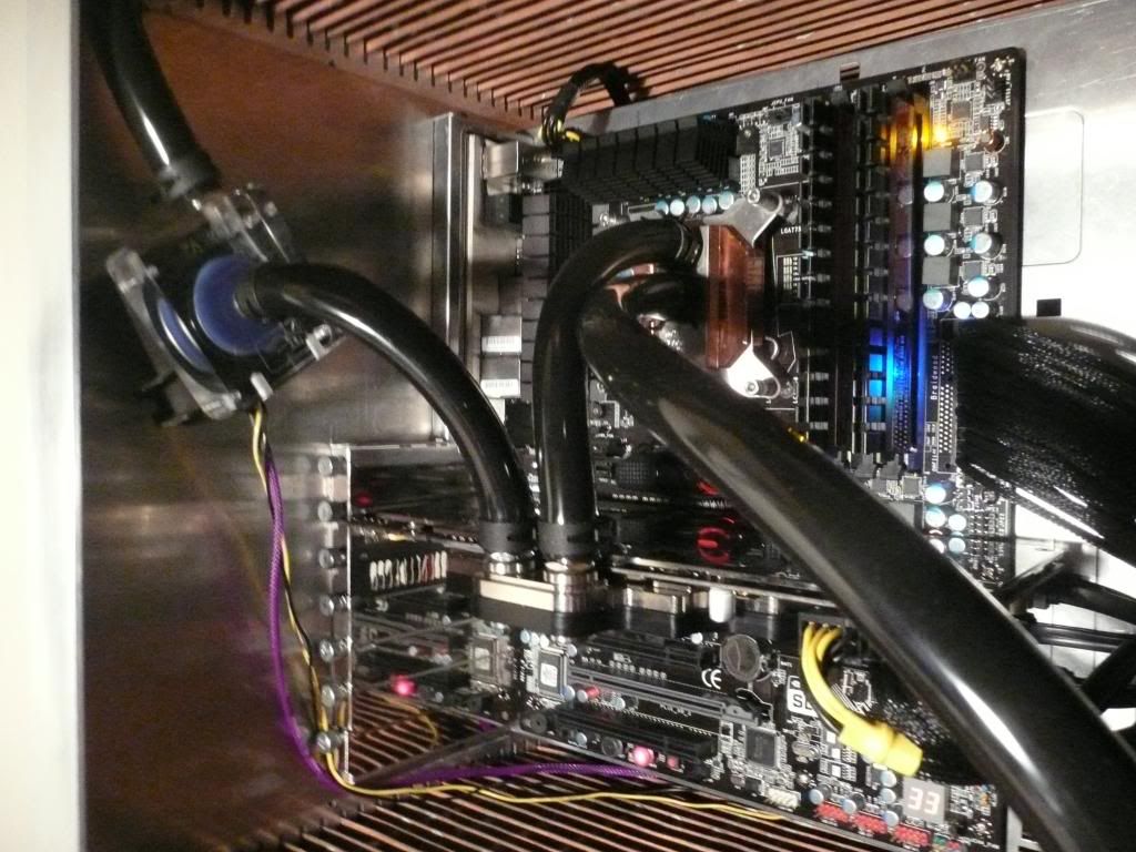
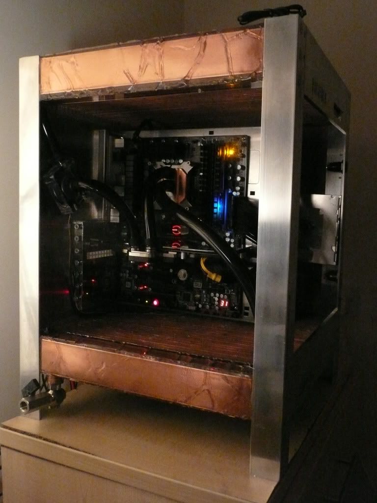
Bit of an update: upgraded my graphics card to a GTX 480 with full cover block. I was a little concerned it might screw up my temps but only seems to have bumped up idle temps 4 or 5C to 32-33C with the GTX480 set to 900MHz core and 2200 for memory at max volts (1.138Vcore). The i5 750 processor is at 4.2Ghz, 1.42Vcore. With Intel Burn Test and Furmark running together I'm getting temps of 49-50C on the GPU and max of 63C on the CPU.
The eagle-eyed may spot the severe kink in the primochill 1/2" ID, 3/4"OD tubing between the GPU block and the pump. Think I may need to go for some 45 degree rotary fittings to solve that.
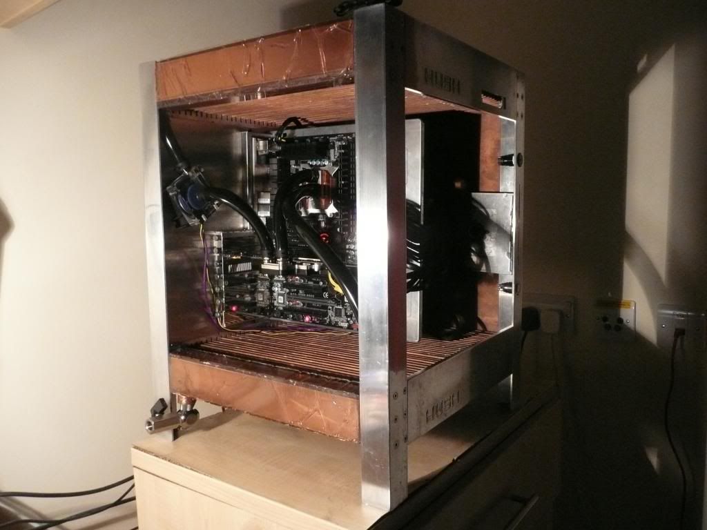
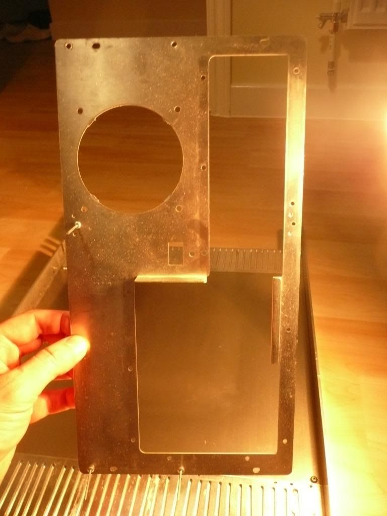
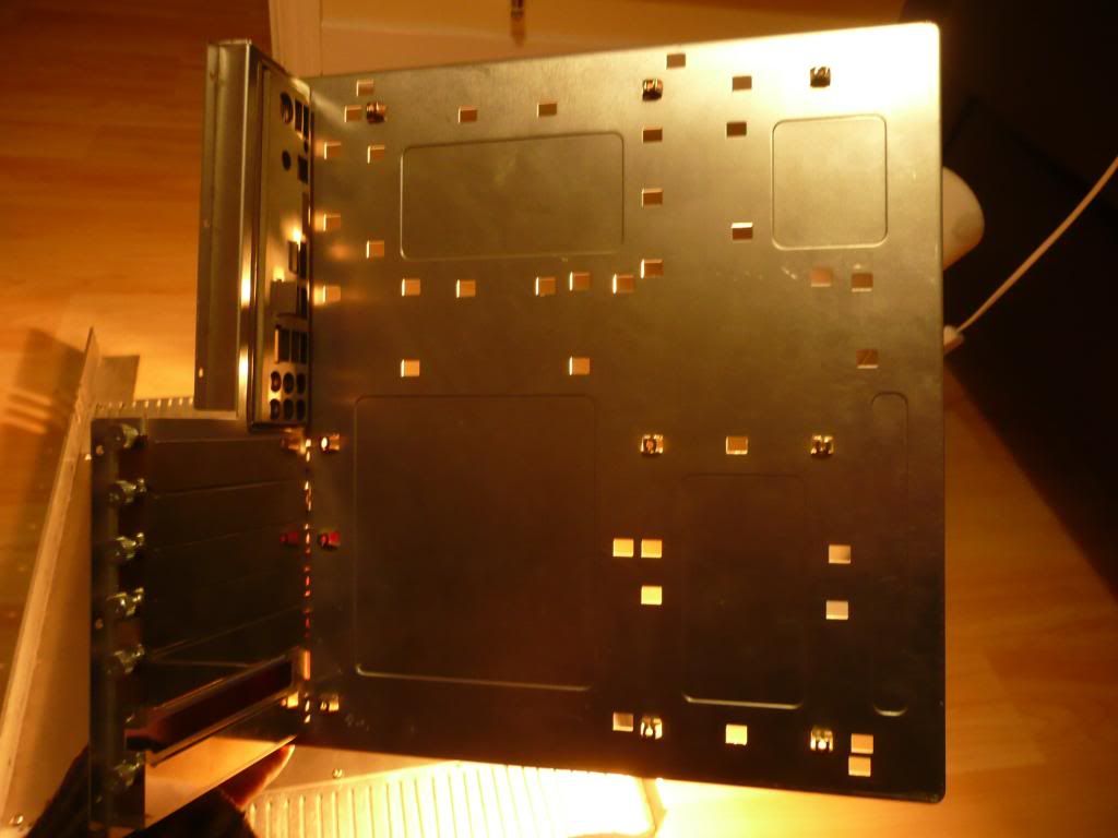
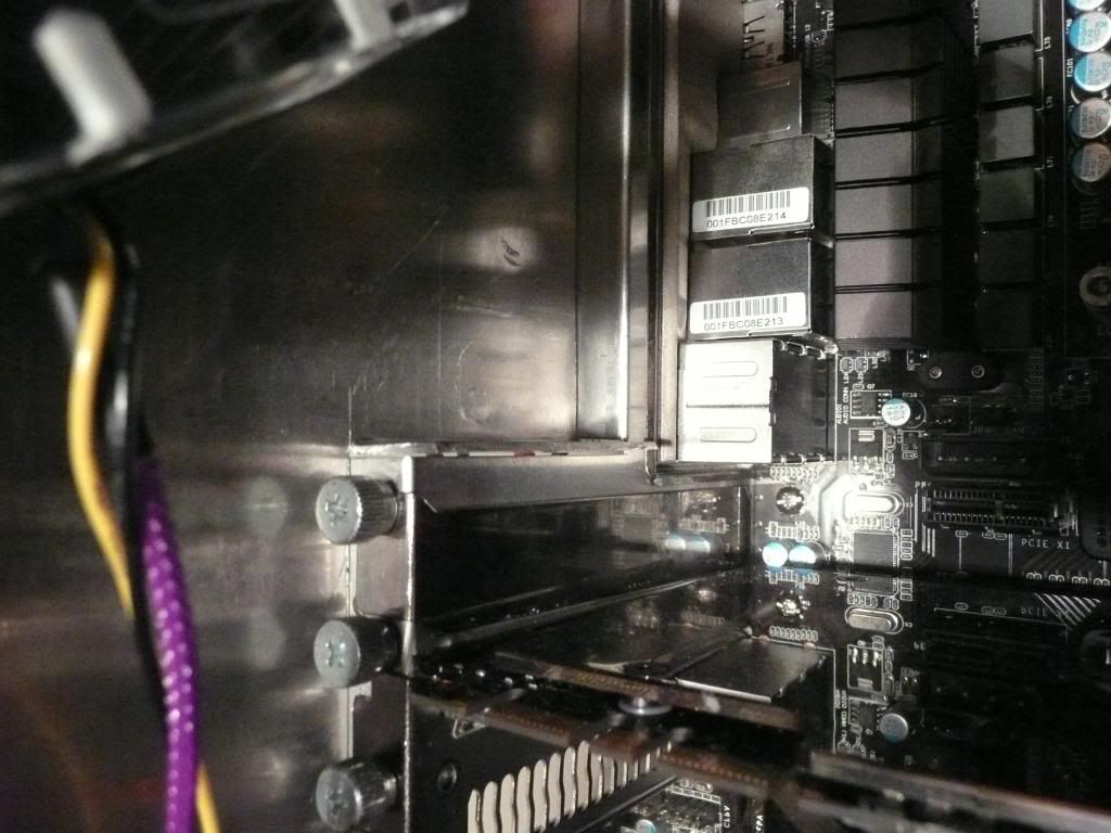
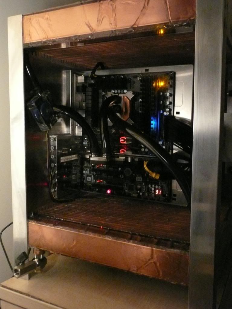
Here's the 1.5mm thick aluminium backplate. I've cut a hole for the pci/io bracket and an extra 1mm width to allow for the motherboard tray. There's also a hole for the PSU to vent through, though I still need to cut slightly into one of the supporting legs for the PSU kettle plug to go through
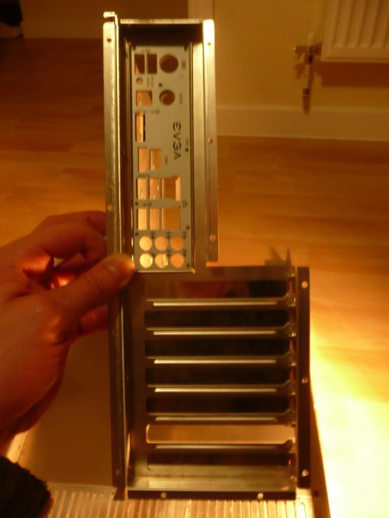
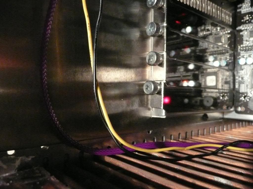
The PCI&IO backplate is attached from the back - it's not attached by screws yet - it'll have some countersunk screws hidden behind the pci bracket thumbscrews.
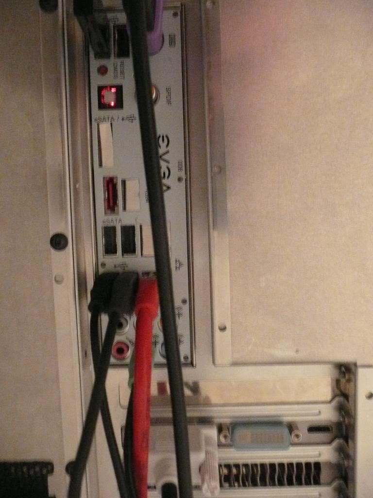
I don't have a metal break, so I clamped aluminium angle with G clamps and bent the flap of the backplate above the PCI bracket to a right angle with a hammer against the clamped alminium angle. Unfortunately I missed a few times, and theres two small dents. I'll try getting rid of them with by clamping the backplate between two flat plates, but if that doesn't work I might need to use filler and spraypaint the backplate...
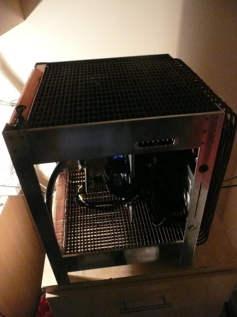
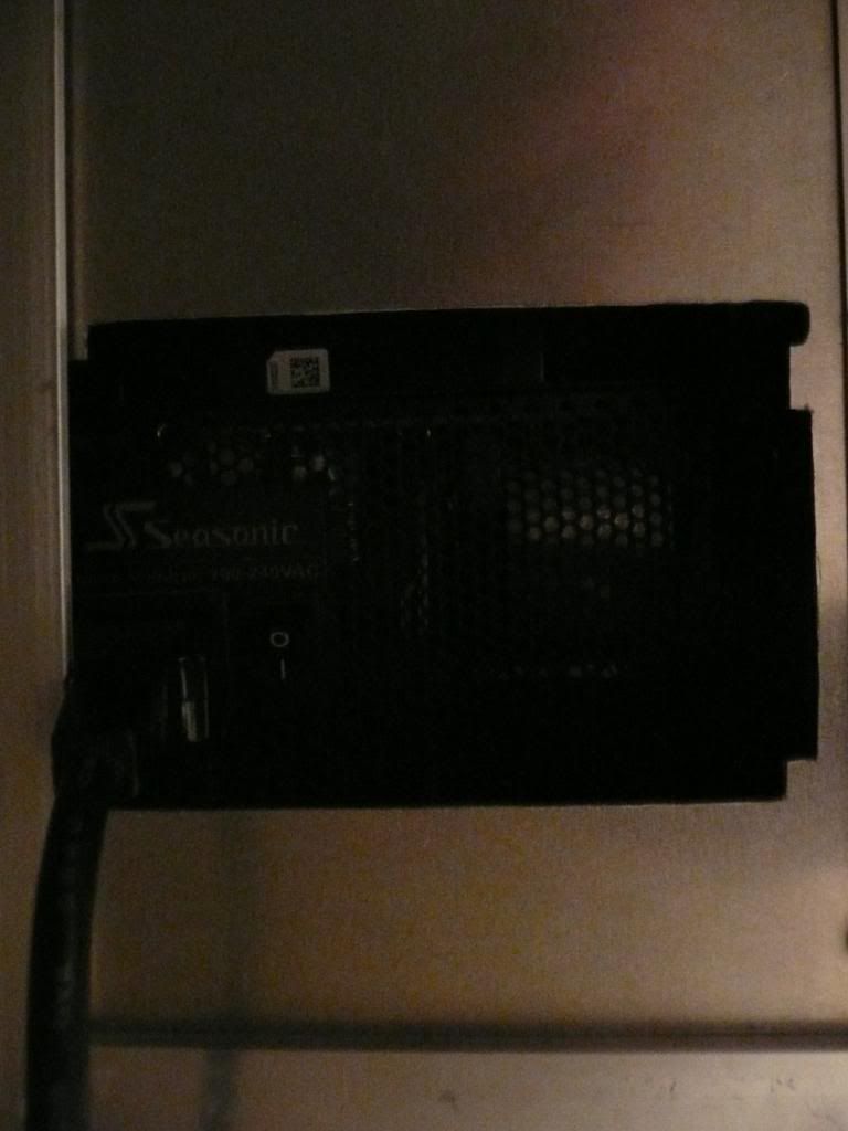
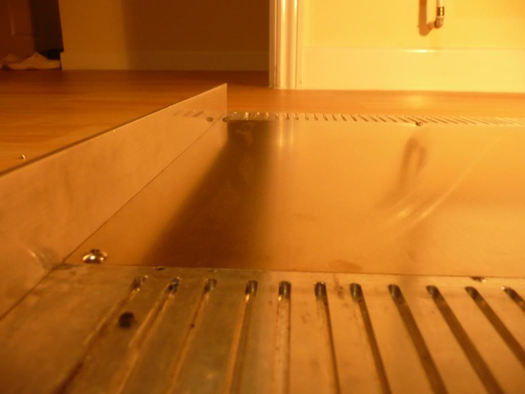
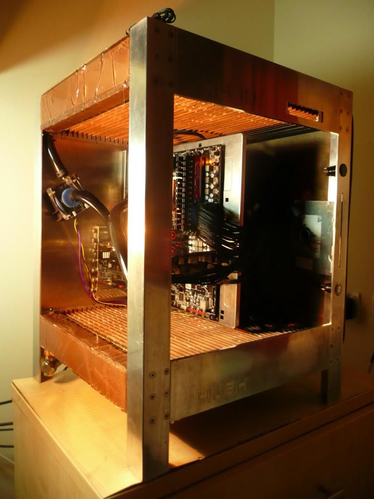
Here's a poor photo of the back of the case:
Not that easy to see, but I've filled in the irregular creases in the polyester coat on the ends. Still needs filling with polyester resin on the top and bottom of the bottom plenum, and then I can sand it down. I'll probably end up spraying the plenums black.
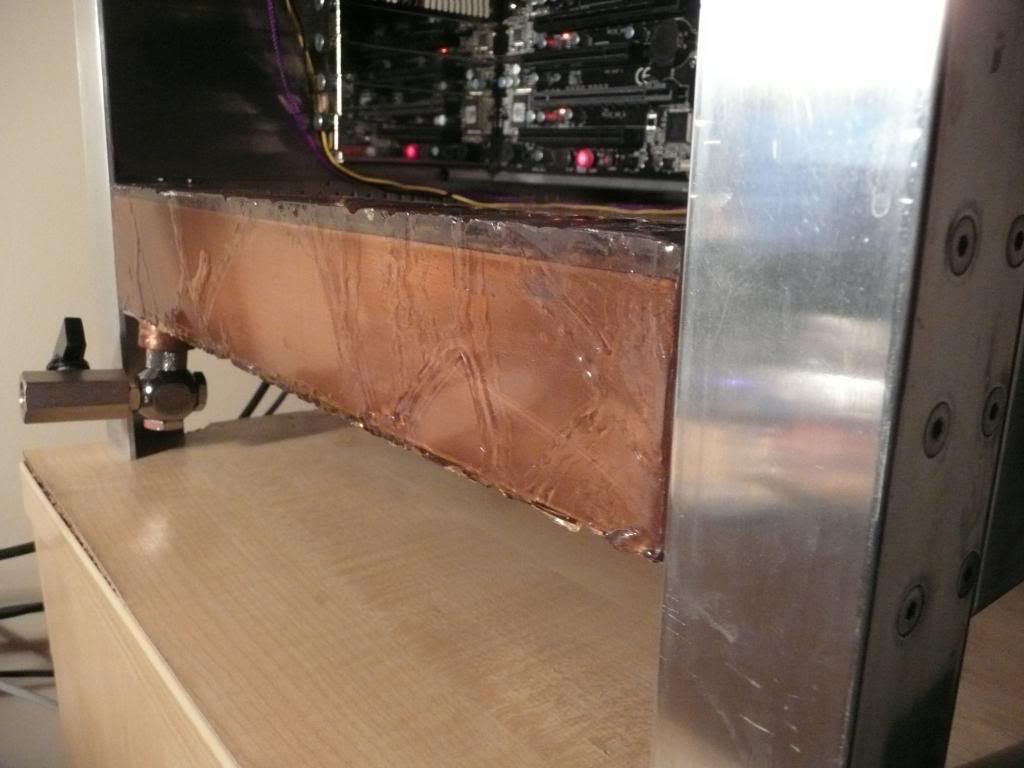
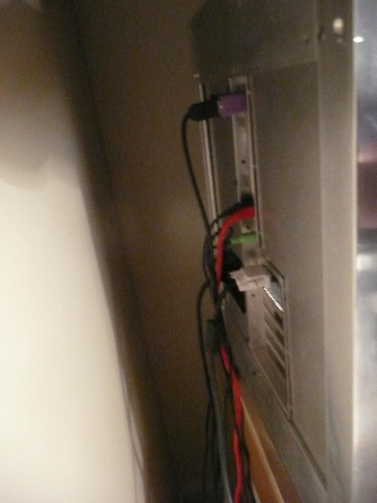
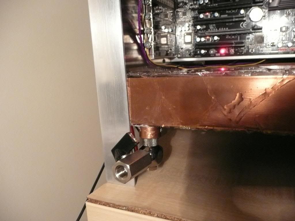
I added a ball valve for draining the loop, attached to a bitspower rotary adapter. I had tried a less compact rotary fitting but it leaked. :/
Hidden away...
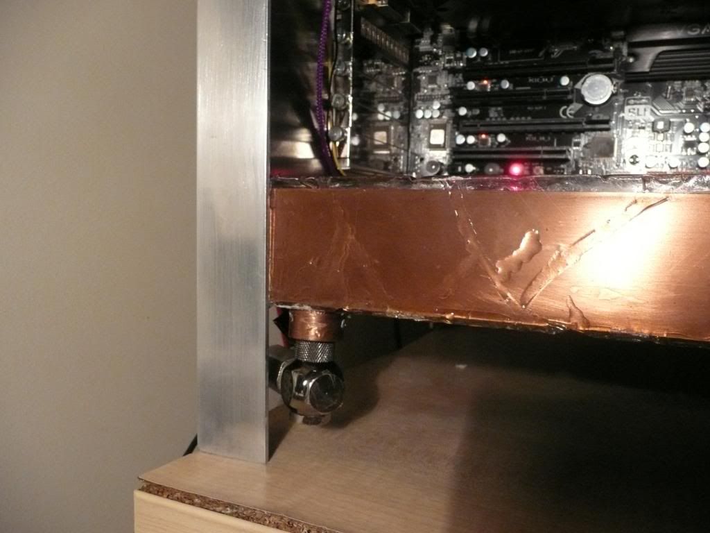
Swiveled round for draining. A 90 degree turn of the black tap and the system drains.
The eagle-eyed may spot the severe kink in the primochill 1/2" ID, 3/4"OD tubing between the GPU block and the pump. Think I may need to go for some 45 degree rotary fittings to solve that.
Here's the 1.5mm thick aluminium backplate. I've cut a hole for the pci/io bracket and an extra 1mm width to allow for the motherboard tray. There's also a hole for the PSU to vent through, though I still need to cut slightly into one of the supporting legs for the PSU kettle plug to go through
The PCI&IO backplate is attached from the back - it's not attached by screws yet - it'll have some countersunk screws hidden behind the pci bracket thumbscrews.
I don't have a metal break, so I clamped aluminium angle with G clamps and bent the flap of the backplate above the PCI bracket to a right angle with a hammer against the clamped alminium angle. Unfortunately I missed a few times, and theres two small dents.
Here's a poor photo of the back of the case:
Not that easy to see, but I've filled in the irregular creases in the polyester coat on the ends. Still needs filling with polyester resin on the top and bottom of the bottom plenum, and then I can sand it down. I'll probably end up spraying the plenums black.
I added a ball valve for draining the loop, attached to a bitspower rotary adapter. I had tried a less compact rotary fitting but it leaked. :/
Hidden away...
Swiveled round for draining. A 90 degree turn of the black tap and the system drains.
Re: Project: Hush!
every time i look at this thread i come away impressed.
Re: Project: Hush!
Has it been finished?
-
=assassin=
- Posts: 243
- Joined: Thu Aug 25, 2005 2:46 am
- Location: Blackpool, England, UK
- Contact:
Re: Project: Hush!
Impressive work, I'd love to see how it looks now.