Ninja/SFF/Single Fan Case.....Getting there.

Enclosures and acoustic damping to help quiet them.

Moderators: NeilBlanchard, Ralf Hutter, sthayashi, Devonavar

Post Reply
Bluefront
*Lifetime Patron*
Posts: 5316
Joined: Sat Jan 18, 2003 2:19 pm
Location: St Louis (county) Missouri USA

Ninja/SFF/Single Fan Case.....Getting there.

Post by Bluefront » Mon Oct 22, 2007 10:50 am

It lives! But only as a cardboard mock-up of a soon-to-be-started SFF project. I've been doing Ninja airflow testing for a few weeks now, and developed this new duct design I call a wing duct. With this P4-2.4 it is running off a 92mm Nexus, controlled by the Intel board fan control (4.5V-12V).

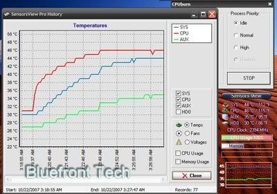
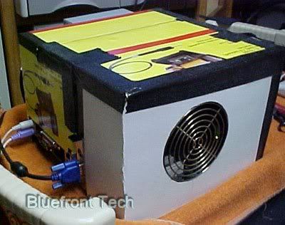
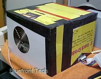
The testing today has an ambient of 27C. With the cardboard case in place as you see it, it idles about 33C, and maxes using CPUBurn about 47C. At that temp the fan is at 12V. If I run the fan off a manual control and leave it at 6V, the temp goes to about 49C max. Under normal usage, I cannot hear this Nexus at all.

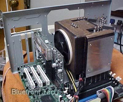
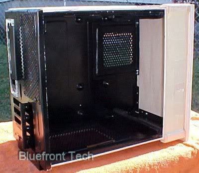
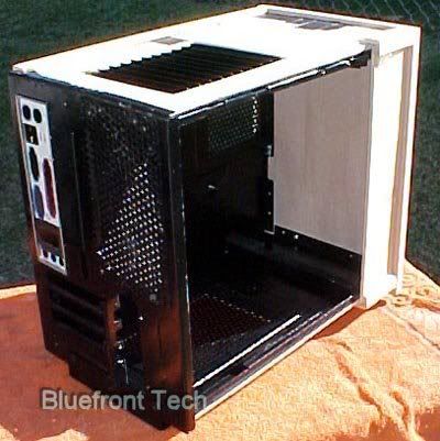
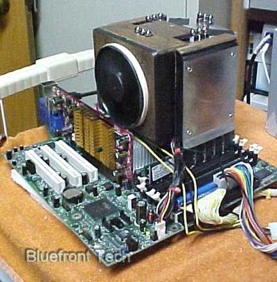
The case measures 10.5x10.5x7.25"......only slightly bigger than the board. The Ninja has about 1/4" clearance on the top. There is enough room to internally mount a 3.5" HD, right over the card area, cooled by the airflow toward the Nexus. If you would use laptop components (like I will), there is enough room for an optical drive, and a HD. All three PCI slots could be used, as well as the AGP slot. There is a low-profile MX400 in there for testing.....a full sized video card can also be used. The airflow over the shorter card is better.

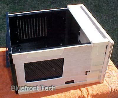
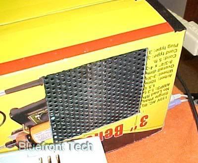
The main thing about this setup.....everything inside the case is in the airflow path. With the wings on the duct allowing airflow toward the ram sticks, and toward the other MB components. The exhaust grill is on there for testing only....it is somewhat restrictive, and will be changed in the completed project. This setup can operate either horizontal, like you see it, or vertical with the exhaust on top, and the intake on the bottom. There is enough room to add other passive intake vents if necessary. And.....a filter could be installed over the intake if necessary. This setup operates on such low airflow, the dust build-up would be minimal.

The 92mm Nexus is probably the quietest fan of it's size available. The Ninja gives it the ability to run at about 5V most of the time, using a 60W CPU, and a low-power video card. The power supply will be a 120W PICO. Like you see it without any internal damping, this is the quietest computer I ever built. When finished it will be mostly wood (1/8" aircraft plywood), with the interior covered with acoustic foam. Of course specifications are subject to change. Stay tuned......

Image

Image

Image

Image

Other photos of the wing-duct

Ninja Airflow Testing Thread

New 3.5" HD mount
Last edited by Bluefront on Thu Nov 01, 2007 1:18 pm, edited 4 times in total.

StApostol
Posts: 39
Joined: Sat Mar 17, 2007 12:57 am

Post by StApostol » Mon Oct 22, 2007 11:02 am

Excellent work!

I am going to copy this for my 24/7 server, I hope you don't mind? :)

Bluefront
*Lifetime Patron*
Posts: 5316
Joined: Sat Jan 18, 2003 2:19 pm
Location: St Louis (county) Missouri USA

Post by Bluefront » Mon Oct 22, 2007 12:30 pm

Go right ahead.......that's why I post pictures. If it works out, report back.

I replaced the restrictive exhaust grill with a less restrictive grill. The temps dropped slightly. Here's a chart I just made......ambient of 26C. I think the "SYS" temp sensor is at the upper right corner of the board. Don't know where the AUX sensor is located. The temps stabilized fairly quickly.....at these temps the fan is about 10.2V. The RPM readings are erratic with this board. That's about 1300rpms.

Image

FWIW.....The Nexus 92mm is rated at 27CFM@12V. That seems to be plenty for this CPU. I have tried this setup with a single low-speed 80mm Yate Loon. The temps raised only a few degrees. That fan is 25CFM......and as quiet as the Nexus. Depending on what CPU use, you might use a stronger fan. 92mm is the max size that fits this duct....but you don't really need a big fan with a Ninja. :D

Oh....this is the first setup I ever designed with a straight-through airflow path. You can look into the intake and see right through the Ninja and out the other side of the case. :D

Bluefront
*Lifetime Patron*
Posts: 5316
Joined: Sat Jan 18, 2003 2:19 pm
Location: St Louis (county) Missouri USA

Post by Bluefront » Tue Oct 23, 2007 9:12 am

I got started gathering a few pieces for this project. If there is any interest, I'll continue to post pictures and instructions on how to build a custom-sized partial wood SFF case.

The first thing to do is to get a general idea about the size of the case, and the MB you want to use. I did that in the previous posts, including building a cardboard test unit......not really necessary, but it might save you from some surprises. I still haven't decided on everything yet, but I'll deal with that as I progress.

You are dealing with pieces that have certain dimensions....notably the I/O ports, and the location of the card slots. These dimensions can't easily be modified.....and are mostly the same for different cases. So.....If you have access to old, used computers, you might find a rear panel you can use....with minor modification/cutting. I found an old Compaq that will work. This particular case could be modded to almost the exact size of the cardboard case. So I cut it up. I might also be able to use the MB back-plate and more from this Compaq case. I'm considering options. But the case will be constructed around this rear panel.

More to come if anyone is interested in the project.....

Image

Image

Bluefront
*Lifetime Patron*
Posts: 5316
Joined: Sat Jan 18, 2003 2:19 pm
Location: St Louis (county) Missouri USA

Post by Bluefront » Tue Oct 23, 2007 11:31 am

A little more about used cases. These things are usually riveted together using 1/8" rivets. To remove, simply drill through the rivet with a 1/8" drill bit.....or .120" if you have that sort of drill index. Harbor Freight sells a nice big set of bits.....$40. Don't go over this size.....you may want to use that rivet hole again.

Be aware than once the case is in pieces, the individual sections bend easily. Here are the tools I used to bend that upper flange 180 degrees.

Image

A small ball-peen hammer, a heavy piece of steel with square edges, maybe available at a machine shop or a place that sells tools for body shops, and a tool from Harbor freight used to hold stuff for welding. It has 3.5" jaws, which I sanded smooth (so it won't scratch the panel). Once bent you can straighten out the bend or edge using the hammer and the heavy piece of steel. You could also use a square piece of dense wood....the steel works easier.

Think ahead before you bend or cut.....a bend can be undone, a cut cannot. This can be a fun easy project, that will look ok when finished, but only if you're careful. :)

joeyl
Posts: 36
Joined: Thu Sep 20, 2007 4:41 am
Location: New Orleans, LA

Post by joeyl » Tue Oct 23, 2007 12:26 pm

cool. I am doing the same with a Compaq desktop, I am keeping the back panel and mobo tray, and using smoked plexi for the other sides.

Bluefront
*Lifetime Patron*
Posts: 5316
Joined: Sat Jan 18, 2003 2:19 pm
Location: St Louis (county) Missouri USA

Post by Bluefront » Thu Nov 01, 2007 12:59 pm

After an extensive series of temperature tests, I've started the final setup. But I've abandoned the idea of a DIY project....too little interest. But I will say a few things about the DIY part.

It's relatively easy to build your own case using a cut-up surplus case. The Back plate and the MB tray are the most difficult to build entirely on your own. This project uses slightly more of the OEM Compaq case.....cut to pieces however.

I'm covering the case with 1/4" oak plywood. It's actually 3/16 thick. You cannot build an entire case of this plywood (without constructing an inner framework of heavier wood)......too flimsy. Now if you use thicker wood of say 3/4", this could make the whole case, but it makes the setup extremely heavy, and extra big. This setup is the size of an Antec Aria. I have a sheet of 2mm thick closed cell foam between the steel and the wood.....cuts down on any vibrations.

The front panel is 1/2" plywood. It is held to the case by screws on the inside, visible in the photos. As I said before, this case performs equally well either horizontal or vertical. On the side with the opening, there is space for a full-size optical drive, and another 3.5" opening.....the pieces mounted sideways. I think the front will be bare....no openings. The ports and switches will be on the top of the section next to the opening.

The perforated aluminum used as passive vents came from an old "C" band dish. I've got a life-time supply of the stuff now.

Anyway I'm willing to answer questions about this setup. The final write-up will probably go in the general gallery section.

Image

Image

Image

Image

Post Reply