
Water Cooling Circuits Analysis (A liquid cooling work log)
Moderators: NeilBlanchard, Ralf Hutter, sthayashi, Lawrence Lee
-
Edward Ng
- SPCR Reviewer
- Posts: 2696
- Joined: Thu Dec 11, 2003 9:53 pm
- Location: Scarsdale, NY
- Contact:
Okay guys, we're live...
I want to know how you guys think I should run these tests. Right now, I'm thinking the following:
1) Full system at idle for minimum 6 hours.
2) GPU Idle, CPU at full blast with CPU Burn K7 mode for minimum 6 hours.
3) CPU Idle, GPU at full blast with RTHDRIBL and jacked up settings (maxed out aniso, maxed out antialiasing, maxed out MIPmap detail, V-sync off, brilinear off, aniso optimization off) for minimum 6 hours--RTHDRIBL in window mode, stretched to 1024x768 in 32-bit mode.
4) RTHDRIBL normal priority, jacked down settings (zero aniso, zero antialiasing, bilinear filtering, lowest MIPmap detail, all optimizations enabled) and CPU Burn K7 mode at idle priority for minimum 6 hours--RTHDRIBL in window mode, stretched to 1024x768 in 16-bit mode.
I will run all these tests at 166*11.0=1833MHz and 1.65Volts (stock 2500+) and 350/1000 (stock 6800 GT). I'm not so sure it would be conclusive to run the GPU at Ultra speeds, even though I can (it's doing 440/1180 right now, which is much higher than Ultra's stock speed of 400/1100), because as Bit-Tech indicated, the GTs are set to run a lower voltage, so even if I ran it as high a speed, it still won't draw as much power/generate as much heat an Ultra. If you guys don't like 2500+, the CPU can be run at any Athlon XP speed grade you guys like except for the stock setting of my chip (stock for my 35watt Mobile Barton is 133*13.5=1800MHz at 1.35Volts and my mainboard only goes down to 1.375Volts). Alternately, I can also do all my tests at the maximum overclock that I have attained, which is 213*12.5=2663MHz at 2.156Volts and GPU at 440/1180, if you guys want. The higher the heat output, the better the chances we'll see wider differences between the different setups.
I've been running Test 4 (load on both, GPU and CPU) for the last few hours and here are my temps (ambient in my room has been 22-25C during the whole time and is holding steady at 24C right now):
CPU (as reported by MBM and ABIT's uGuru): 40C
PWM (MBM/uGuru): 81C
Northbridge (MBM/uGuru): 35C
HDD (MBM via SMART): 35C
GPU (nVIDIA panel): 55C
GPU Ambient (nVIDIA panel): 44C
I tried for higher FSB and 215 works fine, but 217 and 220 don't, even if I max out my northbridge voltage to 1.7V and raise VDIMM to 3.0V. I can boot into Windows at 2.7 and 2.09V (never tried lower), but even at 2.188V, Prime95 doesn't last for over 10 minutes. At my current speed and voltage, Prime95 went for hours. The GPU fails the auto test at 450, so I dropped it back to 440 and the GDDR3 tests clear up to 1180; 1200 doesn't clear autotest. I did additional 3DMark03, Doom3 and Far Cry tests for artifacting/stuttering/freezing and there was zero.
I did as you guys suggested and flipped the side panel fan and heatercore fan, so that the heatercore fan pulls cold air in from the front and blows it straight through the heatercore. The side panel fan, along with the rear fan and PSU fan are now all exhausting. I sealed off the RadBox with box tape and then to prevent dust collecting in it, I then used more box tape to cover up the open adhesive sides of the initial taping, from the inside of the RadBox (initial tape layer was from the outside).
Please realize that I did not get a chance to calibrate the sensors on this mainboard in the same fashion that the sensors on the my SPCR P4 testbed have been calibrated. I did not feel it was 100% necessary because no matter if the diodes are off or not, when I go to change the pump arrangement, if the temps go down 2C, they go down 2C, whether they go down from 40C to 38C or from 50C to 48C is not as important as the fact that they went down 2C.
All in all, I am extremely happy with the system. The best o/c I could get on the air cooling setup was 2533MHz on the CPU and 418/1150 on the GPU. With the water cooling setup and the addition of the MicroCool ChipSinks (don't know if/how much they actually helped), I'm at 2660 and 440/1180. Best part of it all? The system got quieter in the process (the additional 120mm fan does not make as much noise as the 92mm M1B at 12Volts combined with the stock 6800 GT cooler).
Anyhow, please give me some feedback as to what speeds you guys want to see on the CPU/GPU/GDDR3 and what software/software settings you guys want me to test with, as well. I do not know a way to put the absolute maximum heat output load onto both, the CPU and GPU at the same time, and those were my best guesses as to it.
Pictures pending...
-Ed
-
Edward Ng
- SPCR Reviewer
- Posts: 2696
- Joined: Thu Dec 11, 2003 9:53 pm
- Location: Scarsdale, NY
- Contact:
It's anodized aluminum; there was a lengthy discussion I once read on regards to corrositivity and anodized aluminum over, I believe, at the Pro/Forums (Pro Cooling . com). It's actually focused on the CSP-750. If I can find it later I'll link it here, but I'm in the middle of shooting photos for you guys at the moment.
The basic gist (sic?) of it is that the aluminum, when anodized deeply enough, is going to become extremely resistant to corrosion. How that affects the copper remains to be seen, but if I see any corrosion going on, I'll be sure to report it.
The basic gist (sic?) of it is that the aluminum, when anodized deeply enough, is going to become extremely resistant to corrosion. How that affects the copper remains to be seen, but if I see any corrosion going on, I'll be sure to report it.
You did good. No disappointments here. Actually, the temps are better than I expected, but you're right, it's going to be the delta temps that are important between setups.
I don't understand the need for 6 hours for temperatures to stabilize. I'd guess 30-45 minutes would be enough especially if the room temperature was consistent. You could always just watch the temps and record when they stabilize. The motherboard temp is the one I'd guess to take the longest to stabilize.
How warm is the radiator if you touch it? How about air temps as it moves throughout the system? One thing I'd expect you to notice is the delta between idle and load temps for the cpu to be less with water than air.
If you use the Swiftech Hydrx coolant addative, I don't expect you'll ever see corossion if you change the coolant every year. Swiftech has been using anodized aluminum and copper in their blocks for the last 2 1/2 years so they have a very strong warranty interest in preventing corossion.
-
Edward Ng
- SPCR Reviewer
- Posts: 2696
- Joined: Thu Dec 11, 2003 9:53 pm
- Location: Scarsdale, NY
- Contact:
As promised, the photos...
There's a ton of images here, but as usual, I made dial-up friendly versions of the images for the forum here (also to avoid side-scrollage) and then linked a much larger version of the same image to open in a separate window. Beware the desktop image (the shot of my monitor image), as it's larger than the 1024 limit I set for the rest of the high res shots, and, in fact, has not been resampled at all (but I did crop the image to save download time and reduce scrolling); this was done so that you guys can actually read what's on the screen and clearly see what's going on.
There were some shiny surfaces with serious glare and reflections of things like my light diffusing umbrella and even myself; sorry about that, but I was shooting in a bit of a hurry. The dark images shot with little or no light will show lights brighter than reality; this is because I had to set exposure time extremely long (some shots are up to 15seconds of exposure) in order to pick everything up in the dark, so if things like the exhaust fan seem unGodly bright, you know why. The final thing is that there may be some slight misfocusing on shots done into the side of the case; I did my best to minimize this problem by adjusting the f-stop setting to limit etc., but I still don't know how (if?) to manually focus my camera, which means it may have focused on the side panel instead of the object within that I was trying to get.
Anyhow, on with the show...
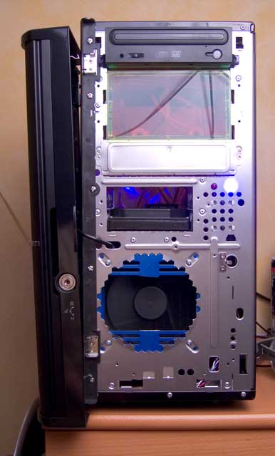
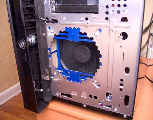
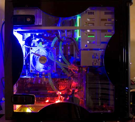
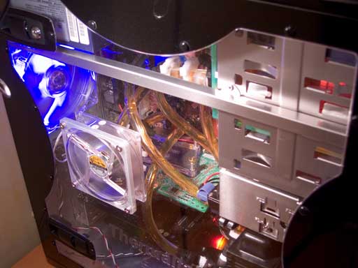
Full view of the front with the bezel & door removed.
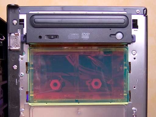
Closer view of the reservoir in operating position. It's UV-reactive green because A) I was originally planning to use this bottle of Swiftech HydrX additive I've got on me and B) they were out of stock on the clear ones.
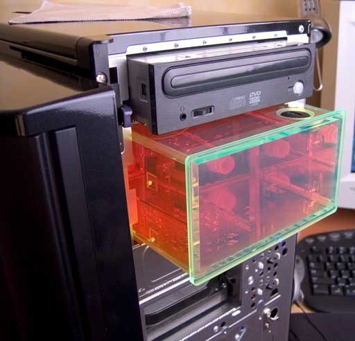
I slid the reservoir out to filling position to get a better view of it.
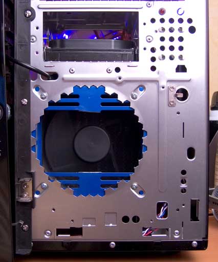
Here's the fan, now reversed.
You can see how I covered the adhesive portion of the RadBox sealing box tape from the inside using smaller sheets of the same tape.
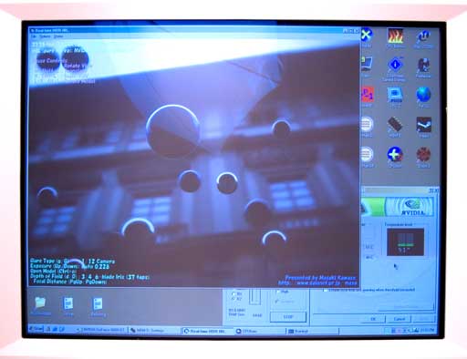
Here's an image of what I'm looking at right now. MBM occupies the tray, while CPUBurn is running along at idle priority with a windowed RTHDRIBL, which it has been stretched to cover 1024x768 pixels in 16-bits, (unfortunately, you can't really read in my photo, but it's in the row of letters at the top left). With RTHDRIBL I can load the GPU while still being able to monitor my temps, including the GPU's, which is why the nVIDIA panel is open there too.
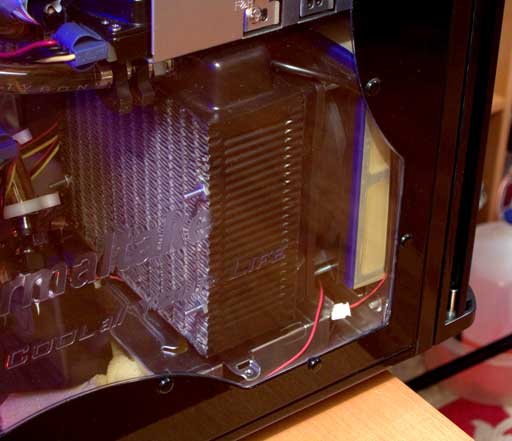
Here's how the RadBox looks now that it's sealed, from the outside.
As you can see, now that the side panel fan has been reversed to blow air out of the case, its label is visible.
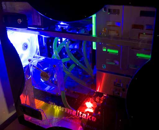
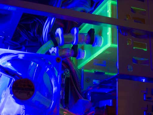
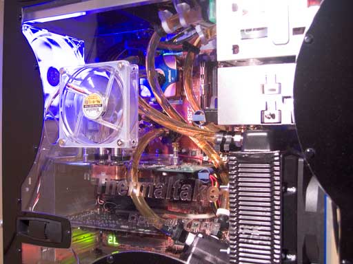
Here's a decent view of the lines to and from the reservoir. You can see that I used a similar method to fix the kinking in the lines on the reservoir as I used for the line from the northbridge block to the GPU block, involving wrapping the 3/8"ID tubing in 1/2"ID tubing and then loosely clamping it. The extra piece of 1/2"ID clamping after the kink fix helps to correct that last flattened portion immediately after the kink fix.
A closer shot of my kink fix.
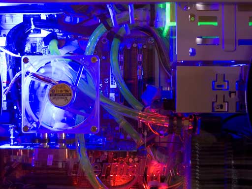
This shot captures almost all the tubing in the entire system.
I utilized a coolant mix based upon airspirit's (of Pro Cooling.com fame) special mix. The mix is 70% distilled water, 20% Dex-Cool (red glycol antifreeze coolant), 5% Hy-Per-Lube brand Super Coolant coolant additive (breaks up surface tension in the blocks and tubing) and 5% biocide of some sort. I did the 70%/20%/5% portion approximately, but I purchased $10 worth of ACD (activated chlorine dioxide--fully noncorrosive!) and it was but two tiny bottles that are to be mixed and added to water to make it potable; the directions indicate 7 drops of each bottle/quart of water. I was running the system without this stuff since it arrived today, so I activated and added 14 drops of each bottle to the 2/5 of the coolant left in my gallon bottle and another 21 drops of each bottle into the cooling system itself; certainly far from 5%, but I think it's okay until I come up with something cheaper.
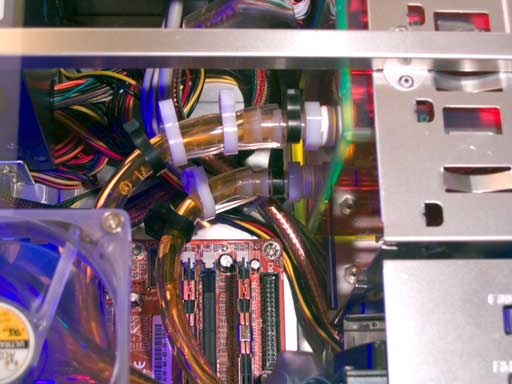
Here's a good, clear view of the fittings for the reservoir. I used teflon tape on the threading of this thing, just as on the pump, to be sure it wouldn't leak. The design of the barbs made it the hardest thing I've ever had to push 3/8"ID tubing onto! At least that makes me confident it won't ever leak...
A clean shot of both lines to the pump; I kept them as smooth as possible.
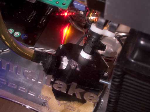
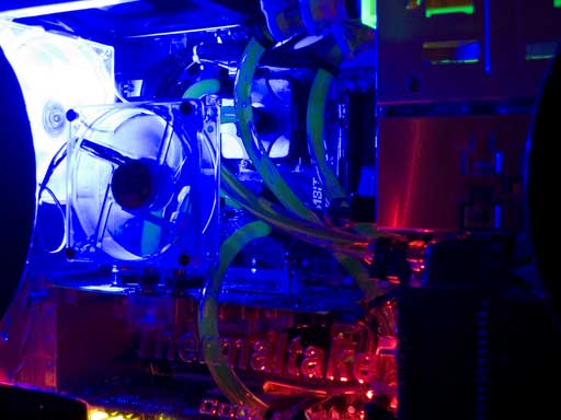
Finally, here's the pump. Yes, I know it's all slanted and stuff. The reason for this is that I have it set up so that when I add the second pump, there won't be excessive tubing going on. What I did to eliminate stress on the northbridge block due to the weight of the pump on the line was to rest it on top of a few pieces of eggcrate foam. This also happens to do a great job of dampening the pump's vibration (cannot hear it at all over the fans, which aren't all that loud, either!). The original setup had the pump getting quite warm (great way to guage the temp. of the coolant! ), and perhaps a fringe benefit of the current location of the pump is that the air coming out of the radiator will sort of cool the pump as well.
-Ed
PS Thanks, 1911. I was noticing that as well (the rate of temp. stabilization), but from what Russ told me, it took hours upon hours for the temps to stabilize on his Reserator; that may be due to the fact that it is passively cooled, though. I'll stick to two hours per test then.
I didn't try touching the radiator yet, as I haven't opened the side panel to check. Somehow I think that openign the side panel will have an effect on the negative pressure, so I didn't try opening it while running yet. I'll take a measurement with the thermal diode on my multimeter tomorrow off the intake tank of the heatercore. I can also get a temp off the pump to see what temp it runs at, since I think people will be interested, now that they know it gets quite hot, being solid anodized aluminum.
I'm quite confident in the quality of airspirit's coolant mix; he is said to seriously know his stuff, and he runs this mix in some crazy system involving feet upon feet of pipes and mixed metal components for months on end.
EDIT: Btw, the ambient in my room is at a rather cold (for me) 22C, and the temps are now:
CPU: 37C
Northbridge: 33C
PWM: 76C (this number fluctuates quite a bit, being the nature of air cooling; the MicroCool MOSFET ChipSinks sure did a great job though, in conjunction with the 120mm exhaust fan, they've cut my PWM figures down over 30C!!!)
HDD: 35C
GPU: 53C
GPU "Ambient": 42C
The test that I started before has been running until now and is still going (Test arrangement 4 from my previous post).
There's a ton of images here, but as usual, I made dial-up friendly versions of the images for the forum here (also to avoid side-scrollage) and then linked a much larger version of the same image to open in a separate window. Beware the desktop image (the shot of my monitor image), as it's larger than the 1024 limit I set for the rest of the high res shots, and, in fact, has not been resampled at all (but I did crop the image to save download time and reduce scrolling); this was done so that you guys can actually read what's on the screen and clearly see what's going on.
There were some shiny surfaces with serious glare and reflections of things like my light diffusing umbrella and even myself; sorry about that, but I was shooting in a bit of a hurry. The dark images shot with little or no light will show lights brighter than reality; this is because I had to set exposure time extremely long (some shots are up to 15seconds of exposure) in order to pick everything up in the dark, so if things like the exhaust fan seem unGodly bright, you know why. The final thing is that there may be some slight misfocusing on shots done into the side of the case; I did my best to minimize this problem by adjusting the f-stop setting to limit etc., but I still don't know how (if?) to manually focus my camera, which means it may have focused on the side panel instead of the object within that I was trying to get.
Anyhow, on with the show...

Full view of the front with the bezel & door removed.

Closer view of the reservoir in operating position. It's UV-reactive green because A) I was originally planning to use this bottle of Swiftech HydrX additive I've got on me and B) they were out of stock on the clear ones.

I slid the reservoir out to filling position to get a better view of it.

Here's the fan, now reversed.

You can see how I covered the adhesive portion of the RadBox sealing box tape from the inside using smaller sheets of the same tape.

Here's an image of what I'm looking at right now. MBM occupies the tray, while CPUBurn is running along at idle priority with a windowed RTHDRIBL, which it has been stretched to cover 1024x768 pixels in 16-bits, (unfortunately, you can't really read in my photo, but it's in the row of letters at the top left). With RTHDRIBL I can load the GPU while still being able to monitor my temps, including the GPU's, which is why the nVIDIA panel is open there too.

Here's how the RadBox looks now that it's sealed, from the outside.


As you can see, now that the side panel fan has been reversed to blow air out of the case, its label is visible.

Here's a decent view of the lines to and from the reservoir. You can see that I used a similar method to fix the kinking in the lines on the reservoir as I used for the line from the northbridge block to the GPU block, involving wrapping the 3/8"ID tubing in 1/2"ID tubing and then loosely clamping it. The extra piece of 1/2"ID clamping after the kink fix helps to correct that last flattened portion immediately after the kink fix.

A closer shot of my kink fix.

This shot captures almost all the tubing in the entire system.

I utilized a coolant mix based upon airspirit's (of Pro Cooling.com fame) special mix. The mix is 70% distilled water, 20% Dex-Cool (red glycol antifreeze coolant), 5% Hy-Per-Lube brand Super Coolant coolant additive (breaks up surface tension in the blocks and tubing) and 5% biocide of some sort. I did the 70%/20%/5% portion approximately, but I purchased $10 worth of ACD (activated chlorine dioxide--fully noncorrosive!) and it was but two tiny bottles that are to be mixed and added to water to make it potable; the directions indicate 7 drops of each bottle/quart of water. I was running the system without this stuff since it arrived today, so I activated and added 14 drops of each bottle to the 2/5 of the coolant left in my gallon bottle and another 21 drops of each bottle into the cooling system itself; certainly far from 5%, but I think it's okay until I come up with something cheaper.

Here's a good, clear view of the fittings for the reservoir. I used teflon tape on the threading of this thing, just as on the pump, to be sure it wouldn't leak. The design of the barbs made it the hardest thing I've ever had to push 3/8"ID tubing onto! At least that makes me confident it won't ever leak...

A clean shot of both lines to the pump; I kept them as smooth as possible.

Finally, here's the pump. Yes, I know it's all slanted and stuff. The reason for this is that I have it set up so that when I add the second pump, there won't be excessive tubing going on. What I did to eliminate stress on the northbridge block due to the weight of the pump on the line was to rest it on top of a few pieces of eggcrate foam. This also happens to do a great job of dampening the pump's vibration (cannot hear it at all over the fans, which aren't all that loud, either!). The original setup had the pump getting quite warm (great way to guage the temp. of the coolant!
-Ed
PS Thanks, 1911. I was noticing that as well (the rate of temp. stabilization), but from what Russ told me, it took hours upon hours for the temps to stabilize on his Reserator; that may be due to the fact that it is passively cooled, though. I'll stick to two hours per test then.
I didn't try touching the radiator yet, as I haven't opened the side panel to check. Somehow I think that openign the side panel will have an effect on the negative pressure, so I didn't try opening it while running yet. I'll take a measurement with the thermal diode on my multimeter tomorrow off the intake tank of the heatercore. I can also get a temp off the pump to see what temp it runs at, since I think people will be interested, now that they know it gets quite hot, being solid anodized aluminum.
I'm quite confident in the quality of airspirit's coolant mix; he is said to seriously know his stuff, and he runs this mix in some crazy system involving feet upon feet of pipes and mixed metal components for months on end.
EDIT: Btw, the ambient in my room is at a rather cold (for me) 22C, and the temps are now:
CPU: 37C
Northbridge: 33C
PWM: 76C (this number fluctuates quite a bit, being the nature of air cooling; the MicroCool MOSFET ChipSinks sure did a great job though, in conjunction with the 120mm exhaust fan, they've cut my PWM figures down over 30C!!!)
HDD: 35C
GPU: 53C
GPU "Ambient": 42C
The test that I started before has been running until now and is still going (Test arrangement 4 from my previous post).
-
Edward Ng
- SPCR Reviewer
- Posts: 2696
- Joined: Thu Dec 11, 2003 9:53 pm
- Location: Scarsdale, NY
- Contact:
Okay, since nobody replied, I'm assuming the tests are fine as I have arranged them, therefore...
Pump Arrangements/Cooling loops:
Scenario 1: Reservoir->Pump1->Northbridge->GPU->CPU->Heatercore->Reservoir
There is no Pump2 in this loop.
Scenario 2: Reservoir->Pump1->Pump2 2->Northbridge->GPU->CPU->Heatercore->Reservoir
Scenario 3: Reservoir->Y-splitter->A/B (A: Pump1->CPU/B: Pump2->Northbridge->GPU)->Y-combiner->Heatercore->Reservoir
CPU: Swiftech MCW-6000A
GPU (and Graphics Memory): Danger Den NV-68
Northbridge: Danger Den Maze4
Pump1: C-Systems CSP-750, "Mark I"
Pump2: C-Systems CSP-750, "Mark I"
Radiator: D-Tek Customs Pro-120 Heatercore
Reservoir: Dual Half-height Bay, "BayRes," UV Green
Coolant: "airspirit's Red Mix:" 70% Distilled Water, 20% Red Glycol (Dex-Cool), 5% Hyperlube (Hy-Per-Lube brand Super Coolant additive) and 5% Biocide (in this case, approx 0.5% worth of ACD--Activated Chlorine Dioxide)
Tubing and Fittings: 100% 3/8" ID x 1/2" OD
Fan pulls cold air in from front intake, past the sealed RadBox, then blows it through a shroud and finally through the heatercore into the case. Side panel 92mmfan, as well as rear 120mm and PSU 120mm fans act as exhausts. Heatercore comes last in the loop instead of first after the pumps because when I go to run the parallel pump branches (Scenario 3), I would otherwise have to move the pump to either before the Y-splitter or after the Y-combiner, and I decided that tube routing would be easier, when switching from Scenario 2 to 3, with the heatercore coming last.
System configuration:
Pertinent Equipment: ABIT AN7 mainboard, AMD 35Watt Mobile Athlon XP 2400+ processor, Two 512MB pieces of OCZ Enhanced LAtency PC3200 DDR SDRAM, XFX-brand GeForce 6800GT AGP graphics adapter, Samsung SpinPoint SP1614N hard disk drive and Fortron FSP300-60PN power supply unit (stock fan replaced with undervolted Globe 120).
CPU: 211FSB * 12.5Multi = ~2640MHz @ 2.156Volts
GPU: 440MHz & Memory 1175MHz @ stock voltages
DDR SDRAM: 11-3-2 CAS2.5 1T Command Rate (CPU Interface Enabled) in Dual Channels @ 2.65Volts
Northbridge: 1.65Volts
Software: Windows XP Pro SP2, Motherboard Monitor, CPUBurn and RTHDRIBL.
This will generate maximum heat, in order to expose the maximum Delta T between pump arrangements.
Tests that will be run:
Test 1: CPU 0% load, GPU sitting idle at the desktop.
Test 2: CPU 100% load (CPUBurn K7 mode, Normal Priority), GPU sitting idle at the desktop.
Test 3: CPU 0% load, GPU under maximum load with RTHDRIBL in 32-bit windowed mode, stretched to 1024x768. nVIDIA settings will be maximum allowed anisotropic filtering, maximum allowed anti-aliasing, maximum MIPmap detail, brilinear filtering disabled and anisotropic optimization disabled.
Test 4: CPU 100% load (CPUBurn K7 mode, Idle Priority), GPU under majority load with RTHDRIBLE in 16-bit windowed mode, stretched to 1024x768. nVIDIA settings will be zero anisotropic filtering, zero anti-aliasing, lowest MIPmap detail and forced bilinear filtering.
Each test will be run for minimum 2 hours and ambient temperature at the case intake will be measured right at the conclusion of the test (the time at which the temperatures are recorded).
Testing has already commenced. I will post results for all four tests for each pump arrangement when all results are in for that particular arrangements. Since I'm still in the early stages of testing and am still using Pump Arrangement 1, any changes that you guys come up with are still valid and perfectly doable.
-Ed
Maybe I'm missing a basic idea of watercooling here... but I would have thought that you'd take the cool input water into the CPU block first, then graphics/nb. Basically reversing the order that you have the waterblocks set in Scenario 1 and 2.
But, if I'm completely wrong here... well, wouldn't be the first time.
But, if I'm completely wrong here... well, wouldn't be the first time.
-
Edward Ng
- SPCR Reviewer
- Posts: 2696
- Joined: Thu Dec 11, 2003 9:53 pm
- Location: Scarsdale, NY
- Contact:
In a properly set up water cooling system, the flow rate is high enough such that the temperature of the water as a whole changes over time; i.e. the temperature of the water throughout the system is within about a degree or so between the coolest and warmest parts...
Anyway, I have the blocks flowing into the heatercore before the reservoir, which is then fed to the pumps. The CSP-750 pumps do not draw much energy and thus do not introduce much heat into the water before moving it on to the pumps, so the water that's been cooled by the heatercore goes to the reservoir and then to the pump, gets maybe some minute, likely unnoticeable amount of heat (again, due to the flow rate) and then moves on to the blocks where they pick up more heat. It's known that the temperature of the water coming out of a block should never be significantly higher than the water going in, with proper flowrates.
-Ed
PS Of course this is the theory that I've been injected with in my readings, and I haven't actually measured the temps of my water in different points of the system to know for sure. Either way, the point of this test is to compare pump arrangements, and as long as the system does not change in component order between pump arrangements, the only important thing is Delta T between setups.
The temperature of the water varies less than 1 degree C throughout the entire water loop. So the order effectively doesn't matter. This is not intuitive. I had to see some heat calculations and think about it initially. If you measure CPU die temps down to 0.1C increments, then flow order can make a very slight difference. The thing to work for is short tubing runs with sweeping bends that minimize the total length of the tubing used and minimize tight bends and turns.Zyzzyx wrote:Maybe I'm missing a basic idea of watercooling here... but I would have thought that you'd take the cool input water into the CPU block first, then graphics/nb. Basically reversing the order that you have the waterblocks set in Scenario 1 and 2..
That does not mean the water temp will only be 1C above the air temperature. The average temperature of the water will be roughly 10C above the air temperature at the radiator depending on the water setup and heat load. The water temp doesn't change much going around the loop.
-
Edward Ng
- SPCR Reviewer
- Posts: 2696
- Joined: Thu Dec 11, 2003 9:53 pm
- Location: Scarsdale, NY
- Contact:
Okay; hit a bit of a snag for the evening and will postpone further testing until tomorrow.
But there is good news; I just saved a bunch of...
...just kidding.
Okay, the true good news is that I managed to complete Test 1 and Test 2 for Pump Arrangement 1, before my issue.
Okay, here's what happened. I was running Test 3 on Gamma Three. Alpha Three was up and running because I had just finished making an update on my site. Sigma One, of course, is on, as it's my 24/7, e-mail, IM, WWW machine. In order to hold my room ambient to ~23-24C, I have my A/C cranked. I share my circuit breaker with the kitchen, which, of course, includes the refrigerator...
...suddenly, the power jumps. I walk in the blind dark to the door of my room and open it up to find that the power in the other half of the apartment is still up--yay, my circuit tripped. Old apartment, two breakers for the whole thing, and each breaker provides up to 20amps before tripping--and they're already upgraded.
So, what did I do? Well I went back into my room, switched all the PSUs to off, switched my A/C to off, and switched all my CRTs to off, even turned off all my lights. I reset the breaker. Turn the lights back on.
I pull out a SeaSonic Power Angel.
Quick test; I plug the Power Angel in between my mains line and Gamma Three, then I turn it on, check the GT's clockrates (just want to make sure that autodetect at startup didn't set my memory back down to 1000) and bring up RTHDRIBL again. Resize it to 1024x768 and then take a look at the Power Angel: 3.88Amps draw.
Wow.
I shut down Gamma Three and remove the Power Angel and then proceeded to pull my bed out of the way, and then installed the Power Angel in between the mains line and my A/C. Crank the A/C and turn it on: 4.3Amps draw.
Damn it!
Gamma Three all by itself, plus the A/C, already draw over 8Amps of my allowance of 20. This doesn't include the refrigerator in the kitchen (which is probably what finally tripped the breaker when the compressor clicked on). Nor does that include the 22" CRT hooked up to Alpha Three at the time, or Alpha Three, or Sigma One.
Guess this means I can't turn on Alpha Three so long as a test is running on Gamma Three!
Anyhow, I'm allowing two hours per test and it's already 12:30AM, so I'm not restarting Test 3 tonight. Guess I'll get moving on it again tomorrow.
How crazy is this?!?
-Ed
Congratulations on your setup Edward, it looks really neat & tidy
I must say though, I did expect your temps to be higher considering you've made what I consider to be a few pretty important design bloopers, namely:
- Pump seems rather wimpy for a 3 block system with a reservoir.
- Rad is on the small side for a hot processor & videocard and the fan should be pulling, not pushing.
- The northbridge block is basically just addding extra heat to your loop, a passive heatsink could do the job just as well.
- 3/8" tubing, enough said.
- Bay reservoirs are *notorious* for leaking.
Incidentally what kind of fan are you using on your rad and how fast is it spinning? I reckon with a better setup you could use a much quieter fan running at 5v and still get results as good or better..
It's great that the system performs up to expectations but I think the above points needed to be mentioned for the benefit of others reading the forum who might be thinking of setting up their own DIY system.
All of this reminds me that I'm yet to post pics of my completed DIY watercooling setup - hopefully I can get access to a decent camera soon because my webcam won't cut it
On the positive side, if you ever decide to upgrade that system of yours it has a lot of headroom for improvement!
-
Edward Ng
- SPCR Reviewer
- Posts: 2696
- Joined: Thu Dec 11, 2003 9:53 pm
- Location: Scarsdale, NY
- Contact:
Personally, I think that I've so far proven that the pump is not as wimpy as you may believe.
Of course I'm under the assumption that you're not comparing the CSP-750 to anything accept pumps that are similarly priced, similarly sized and similarly quiet.
The combination of those three attributes are, after all, the primary focus points of that pump. Are there pumps that are as cheap? Sure. Are there pumps that are as powerful? Most certainly. Are there pumps that are as quiet? Not very many. Are there pumps that are as compact? I don't know of any, but I haven't looked that hard. Are there any pumps that size, that quiet and that cheap that do such a great job moving water through a system like mine?
You decide that one for yourself. As far as I'm concerned, this is the pump for me...
Just wait 'til we see the performance of the dual pump arrangements.
And let's not forget the convenience of these being 12Volt pumps. How much is a relay costing these days? How about relays for two pumps?
And then the Mark II model will report its activity as a fan speed through the third wire; I don't yet know of any pump that does that (but as I said, I've not done an extremely exhaustive search--I'll admit that). No, my Mark I CSP-750s don't do it, but the Mark II models will, and I'm pretty much hell bent on buying me a pair of those once they're out.
-Ed
-
Gooserider
- Posts: 587
- Joined: Fri Aug 01, 2003 10:45 pm
- Location: North Billerica, MA, USA
- Contact:
Well Ed, the photos you show seem to suggest that the setup I suggested (rad against the front wall, fan inside sucking through rad into case via deep shroud - see earlier post) would work, though it would need some additional metal work. Enlarging the present fan hole in the front wall to match the rad face would not have a significant effect on the case strength. Making the fan blow through the rad as you have it now is mixed, and normally I would say it was a bad thing, however with the rest of the fans in the system exhausting, you have effectively created a sort of 'push-pull' setup which is one of the better methods of running fans per the real hard core 'jet-engine' enthusiasts.
However given that you have reasonably good results at present, I can see postponing any changes until the next round of enhancements.
In terms of test duration, most seem to be longer than a couple of hours, but I'm not an expert. The key thing IMHO is that all temps should be very stable at whatever time you choose. For methodology, again I don't think it is real critical as long as it's consistent - However you get there, I would like to see an idle temp, a 'full load' temp, and possibly a couple of points in between. What you describe sounds like a reasonable effort at that.
I would say that the only major concern I have with the current setup as a test platform is whether or not you have enough 'headroom' to show valid results. If the rad is already pushing out as much heat as it can given the current fan setup, adding more pump power isn't going to give a meaningful results change. Think of it as being like putting a really fast diskdrive on a CPU bound system - you aren't addressing the bottleneck so the system speed doesn't change...
One of the things that Bill A's testing has shown is that any given rad / fan setup has a very sharp diminishing returns point beyond which increasing coolant flow doesn't noticeably improve cooling. He also said that airflow was usually the limiting factor in any given setup.
Gooserider
-
Edward Ng
- SPCR Reviewer
- Posts: 2696
- Joined: Thu Dec 11, 2003 9:53 pm
- Location: Scarsdale, NY
- Contact:
Gooserider; was adding to my last reply by edit when the e-mail came in notifying me of your post; will address it after this:
---Copied & Pasted as PS from last reply---
I do not feel the need to address the other stuff in this thread. My system itself is not the primary focus here, as has been discussed before. It's not about Ed's water setup. It's about what happens when you run two CSP-750s instead of just one, and what happens when you switch from two pumps in serial to two pumps in parallel.
I agree on the air flow being backwards; I've read that it should pull through and I'm sure it works better, but I did not have time to screw around any more with the heatercore assembly--I wanted to get this show on the road already. Same goes for trying to fit in a larger heatercore; when I get the time and energy to bust up more of my case to cram in some uber ultra extreme gigantor heatercore from a Peterbilt, fine, I'll do it, but not now, not until this circuit comparison is done, because it just isn't pertinent to the test. As it is I plan to change out the duct for a better one; considering how much trouble it will be to undo the RadBox now that it's sealed up with box tape inside and out, I'm not doing it untul it's time and I'm not going to make minor changes when that time comes.
I do not wish to discuss tube diameter; 3/8" was much easier to work with, and every single part of my cooling setup uses 3/8" fittings. Considering the blocks I chose, 3/8" is perfectly adequate. Had I blocks designed for 1/2" instead, I'd have considered going 1/2". There's no way I'm going bigger than 1/2" and I do not see any reason to. Using 3/4" tubing when all your blocks aren't even designed for anything over 1/2" is ludicrous. The minor improvement improvement in performance is not worth the nightmares in routing, fitting, adapters etc. etc. to use something like that. Do you think that using 1/2" tubing would change whether or not dual pumps is better than single? Would it change the results comparing serial to parallel? I doubt it.
Whether or not the northbridge needs cooling under such extreme overclocking conditions has been under debate before, is currently still under debate, and will likely be under debate forever. I'm not going to delve into that at this time. Needless to say, the block was relatively cheap, and the heat it introduces into the system is peanuts compared to the CPU or GPU.
Quieter fan? Sure--the day I decide to water cool this system for silence without headphones on my head.
---End Paste---
Obviously we've reached a concensus that the heatercore/fan assembly can be left alone for the time being (assuming it does not heavily affect the test outcome). That's nice.
Okay, fine. No set duration. When it appears stabilized, that's it. Whether it's 2 hours or 48.
If your concerns about heatercore capacity limiting my test results turn out true (i.e. the results for all three arrangements are, within margins of testing error, the same), then consider the test null and void. Sorry, but I did my best, unless somebody else is going to foot me the cost of a better heatercore (in that case I'll just set it up outside of my case with a minimal tube run, run the full battery of tests on the 3 pump arrangements, and then call it that). How much more can you ask of someone who's a first time water cooler and has a massive backlog of other reviews to take care of (I have samples of Cooler Master CoolDrive 6, Aerogate 3 and Ultra Vortex all sitting around begging for attention)?
-Ed
EDIT: PS, did I mention I work freelance as a desktop artist and am also helping my dad with a small task of opening a restaurant? Because I am. Anyone else want to tackle my full list of responsibilities while doing a better job of this test? Feel free to let me know.
rather than compromising either way, since this is just a test, why not cable tie the rad to the front of a regular fan? will take all of two minutes, no more case mods/work needed, and will definitively eliminate the rad as a bottleneck...
and i dunno how you're going about scheduling/doing the actual tests, but if you use a 5 gallon pail or something ridiculous as a res, it should make it pretty easy to get stable temps, will just take all day to get there (ie start in morning, check it 12 hours later, small diffs in ambient shouldn't even matter unless it goes from sun shining on your case to overcast all day)
and i dunno how you're going about scheduling/doing the actual tests, but if you use a 5 gallon pail or something ridiculous as a res, it should make it pretty easy to get stable temps, will just take all day to get there (ie start in morning, check it 12 hours later, small diffs in ambient shouldn't even matter unless it goes from sun shining on your case to overcast all day)
-
Edward Ng
- SPCR Reviewer
- Posts: 2696
- Joined: Thu Dec 11, 2003 9:53 pm
- Location: Scarsdale, NY
- Contact:
I'm not so sure blowing a room fan at the little heatercore is any better than the current arrangement, lol! In this case, I would have to agree that the fan is not the problem, the heatercore is.
I'd have to have like $80 worth of ACD and another $30 worth tof Hyperlube Super Coolant, along with another $10 worth of Red Glycol to mix up with the sufficient distilled water (at least that's cheap!) to make that much coolant.
I'd have to have like $80 worth of ACD and another $30 worth tof Hyperlube Super Coolant, along with another $10 worth of Red Glycol to mix up with the sufficient distilled water (at least that's cheap!) to make that much coolant.
-
Edward Ng
- SPCR Reviewer
- Posts: 2696
- Joined: Thu Dec 11, 2003 9:53 pm
- Location: Scarsdale, NY
- Contact:
Thanks, DryFire! I'm glad it's good use to you. I really am. 
Oh and Bosk, the fan in my heatercore assembly is the stock 120mm fan in the back of the Sonata. The rear 120mm fan is the stock Antec blue LED fan in the front of the Super LAN Boy. The side exhaust is an AcoustiFan AF92CT with its thermistor lodged into one of the Microcool MOSFET ChipSinks.
all three fans are at 12Volts.
The one undervolted fan is the 120mm Globe inside the PSU; it's attached to the self-regulated line within the PSU via one of the resistors included with AcoustiFan kits.
-Ed
-
Edward Ng
- SPCR Reviewer
- Posts: 2696
- Joined: Thu Dec 11, 2003 9:53 pm
- Location: Scarsdale, NY
- Contact:
Okay, everyone; got some juicy numbers to share and I would like some sort of group analysis on this before making a decision as to what to do next.
Here they are:
I think it's pretty clear what we're looking at but I'll explain it anyway.
Test #: That's the specific test run; in short, 1: all idle 2: CPU load, GPU idle 3: GPU load, CPU left to do nothing but help thew GPU 4: load on both
CPU: Temp. from CPU as reported to Motherboard Monitor by the mainboard.
Northbridge: Temp. from the chipset as reported by my ABIT AN7's uGuru chip, supported by Motherboard Monitor.
MOSFETs: Temp. from the MOSFETs, again courtesy of uGuru and Motherboard Monitor.
HDD: From Motherboard's SMART support.
GPU: Straight from nVIDIA's own panel.
GPU Ambient: Also from the nVIDIA panel.
Room Ambient: As measured using my multimeter/thermal probe from within inches of the front intake at the time the temperatures were recorded.
As we expected, the idle operating temps were the lowest (Test 1), even though ambient temps were highest at the time.
Pure CPU load test shows the highest CPU, northbridge and MOSFET temps.
Pure GPU load test shows the highest GPU and GPU Ambient temps (particularly considering the low ambient at the time).
Unfortunately, the dual load results came out as I expected; it looked mostly like a sort of weak GPU load. I pretty much expected this because I start RTHDRIBL up and resize it before clicking Burn! and due to its idle priority, it takes a while to even start burning--I believe RTHDRIBL is already eating pretty much all of the CPU's cycles. The bad thing is that, obviously, RTHDRIBL cannot make the CPU run nearly as warm as CPUBurn can.
I'm thinking of ditching Test 4 all together, since it's not particularly conclusive. If anybody can come up with some sort of time demo or loop I can run with a free game demo or one of the following games that I own:
Far Cry
Doom3
Unreal Tournament 2004
Battlefield 1942
X2: The Threat
I can also consider using something like that to come up with a new Test 4.
I don't think it necessary to record the hard drive temps; they're erratic and not relevant (always jumps between 33 and 35; what's wrong with 34?!?). MOSFET temps are pretty important, but the problem is that, due to their small size and air cooled nature, plus serious tendency to fluctuate in temperature very rapidly, I can look at it, it reads 76C, I turn around to type it into my spreadsheet, and suddenly it is reading 78C, then I turn around to change it to 78C, and then I go back and now it's 73C. Basically, take MOSFET temp as a general measure, but it's more like +/-~3C.
I've found the GPU and GPU Ambient to be very stable as I read them. CPU temp. is also quite stable. The somewhat problematic one appears to be the Northbridge; it's stable whenever I look at it, but for some reason, the High part of MBM's log shows that somewhere along the line, occasionally, the Northbridge sensor randomly spikes to something crazy like 120C. Basically, I can also use the Average, Low and High figures to help confirm the numbers I read for the CPU, but not for Northbridge.
I figure, however, that the two most important figures for you guys is the CPU and GPU, anyway. Does anyone know of a plug-in for MBM that can read and log the temp's from my GPU? It's much better than just having the immediate figure, being able to look at a history of it.
Finally, I am seriously considering running two more passes of Test 1, 2 and 3 on Arrangement 1 before draining it out and adding in the second pump. I feel that it's really more secure to have three figures for each Test, to be sure that we're getting fair accuracy, even though I'm letting these tests run for well over two hours. If you guys would prefer I just jump into the serial pumps test sooner though, I could do that as well--or maybe I run just one more pass of tests, instead of two...
Please post your comments, thoughts, ideas, suggestions, whatever. I think that with more feedback from you, the readers, I can render this test more useful, and focus more precisely on the things that matter (at least, maybe....
-Ed
You're right. I forgot about the looping having to be enabled.Edward Ng wrote:Don't I have to register 3DMark03 to get the looping option?
I remember that the opening scene of "unreal" was a good system test back in 1998/1999. It was a good stability/stress test for computers; if it didn't crash overnight, you were stable! Do the newer versions of unreal tournament have such an opening scene or demo loop?
-
HammerSandwich
- *Lifetime Patron*
- Posts: 1288
- Joined: Sat Oct 25, 2003 3:21 pm
- Location: 15143, USA
- Contact:
Ed, that looks much better than where you were before! Good work. And DTEK just put the Mark 2 up for preorder at $37.
Bosk, while your criticisms are valid, I'd say you've isolated each component rather than considering the overall system. For example, if the pump has low flow, will 3/8" tubing be a restriction? If a passive heatsink can cool the NB well enough, is the NB block really adding significant heat to the water?Bosk wrote:...you've made what I consider to be a few pretty important design bloopers..., namely:
-
HammerSandwich
- *Lifetime Patron*
- Posts: 1288
- Joined: Sat Oct 25, 2003 3:21 pm
- Location: 15143, USA
- Contact: