
Hi guys. Hopefully some of you are knowledgable on these things!
Basically I want to try an run my atx pc off one. The specs arn't special (Gigabyte GA965PAS3 / 4gb / E2160 / 8600gt / 5400rpm 2.5" HD) and so I have a power monitor showing my system using aroun 90-100w on idle and 130w at load.
Because of this, o people think I would be ok running off a 150w Pico or would it be a little safer to look at 180/200w??
Thanks
PicoPSU Question.
Moderators: NeilBlanchard, Ralf Hutter, sthayashi, Lawrence Lee, Devonavar
-
electrodacus
- -- Vendor --
- Posts: 372
- Joined: Sun Jul 12, 2009 10:30 am
- Location: Canada
- Contact:
Well, he said "good 200W ATX power supply". There is PW-200 series made by the same company as picoPSU (mini-box). But electrodacus doesn't want to recommend it. You can search the forums for various experiences people have had with it.osian wrote:So it's a no to any dc-dc adapter type psu?
Another alternative is to use a separate power source for the CPU, provided via the P4 connector on your motherboard, and use picoPSU for the main power (20 or 24--pin ATX connector on your motherboard).
You can use two separate external power bricks for the two sources, or one big power brick such as Dell DA-2 but split the power into two strands. Search for DA-2 on the forums for more info.
Uday
AuraAllan, Thanks for joining us. I have been meaning to ask a couple of questions about your system.AuraAllan wrote: I ran this system of a PV-200-V and a Dell DA-2 brick with no problems.
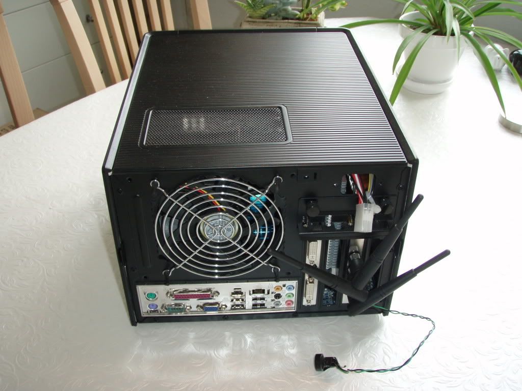
What is the type of the junction box that you used to splice the wires from your mating connector to the PW-200's leads? And, do I see some kind of a red connector/switch for the trigger/remote line of DA-2?
I am also curious about the green/red braided lead that seems to connect to the black connector at the back (2.5mm jack again)?
That was a real sexy system you built there! Pity that you dismantled it.
Uday
Sorry for hi-jacking this thread a bit.
Will start a thread about it if I decide to do another build in the NSK.
If you have anymore questions for this build (or suggestions for a new build) please use my NSK1300 thread.
It's a terminal stripreddyuday wrote:What is the type of the junction box that you used to splice the wires from your mating connector to the PW-200's leads?
No. It's a (what is the English word for this? I don't think it's called a terminal strip) used for shielding of a spare wire.reddyuday wrote:And, do I see some kind of a red connector/switch for the trigger/remote line of DA-2?
The one hanging out the back in this picture? It's the power button.reddyuday wrote:I am also curious about the green/red braided lead that seems to connect to the black connector at the back (2.5mm jack again)?
Thanks. I've been thinking about doing a new build in the case. Also thinking about redoing the case again but i'm not sure.reddyuday wrote:That was a real sexy system you built there! Pity that you dismantled it.
Will start a thread about it if I decide to do another build in the NSK.
If you have anymore questions for this build (or suggestions for a new build) please use my NSK1300 thread.
-
Firetech
- Friend of SPCR
- Posts: 680
- Joined: Fri Dec 16, 2005 4:50 pm
- Location: Sydney, Australia
- Contact:
It's called a BP Connector here in Australia. I don't recall ever using them as a sparky in the UK so maybe he can just use an insulated crimp connector instead.AuraAllan wrote:No. It's a (what is the English word for this? I don't think it's called a terminal strip) used for shielding of a spare wire.